Invented by Kenneth L. Kramer, Marshall S. Dahneke, Reed N. Wilcox, Franz Gaag, David T. Schwanemann, Rainer B. Teufel, Peter A. Koloski, Thornton K. Lothrop, Ryan R. Berger, Hill Rom Services Inc
One of the main benefits of chairs with movable arm sections and table sections is their versatility. These chairs can be used in a variety of settings, from offices and conference rooms to classrooms and training centers. They are also ideal for use in home offices, where they can provide users with a comfortable and ergonomic seating option that allows them to work more efficiently.
Another benefit of these chairs is their convenience. With movable arm sections and table sections, users can easily adjust the chair to their preferred position, whether they need to work on a laptop or take notes on a piece of paper. This makes these chairs ideal for use in settings where users need to switch between different tasks throughout the day.
In addition to their versatility and convenience, chairs with movable arm sections and table sections are also designed to be comfortable and ergonomic. They feature adjustable armrests and backrests, as well as padded seats and lumbar support, to ensure that users can sit comfortably for extended periods of time.
Overall, the market for chairs with movable arm sections and table sections is expected to continue growing in the coming years. As more people seek out comfortable and convenient seating options for their homes and workplaces, these chairs are likely to become increasingly popular. Whether you are looking for a comfortable and ergonomic seating option for your home office or a versatile and convenient chair for your conference room, chairs with movable arm sections and table sections are definitely worth considering.

The Hill Rom Services Inc invention works as follows
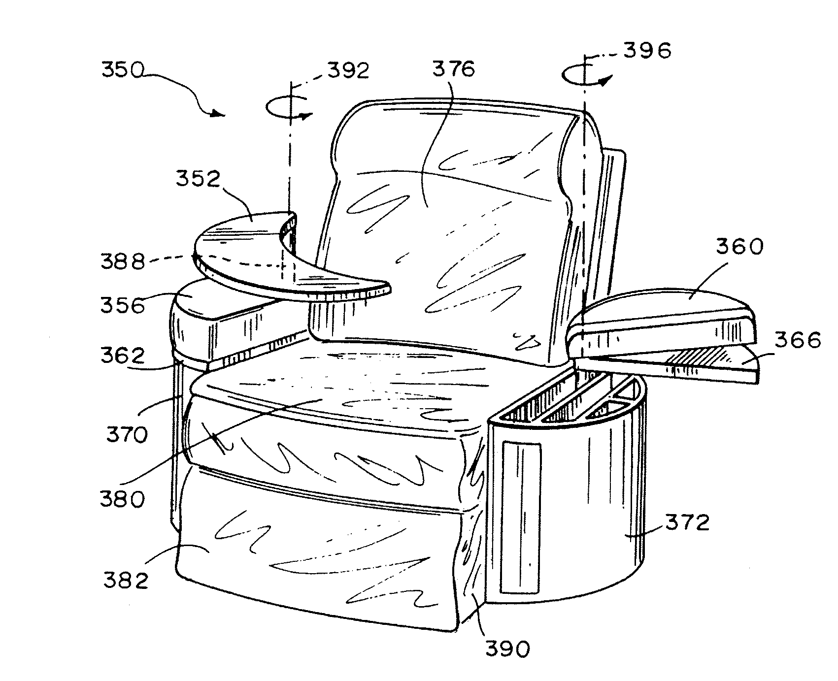
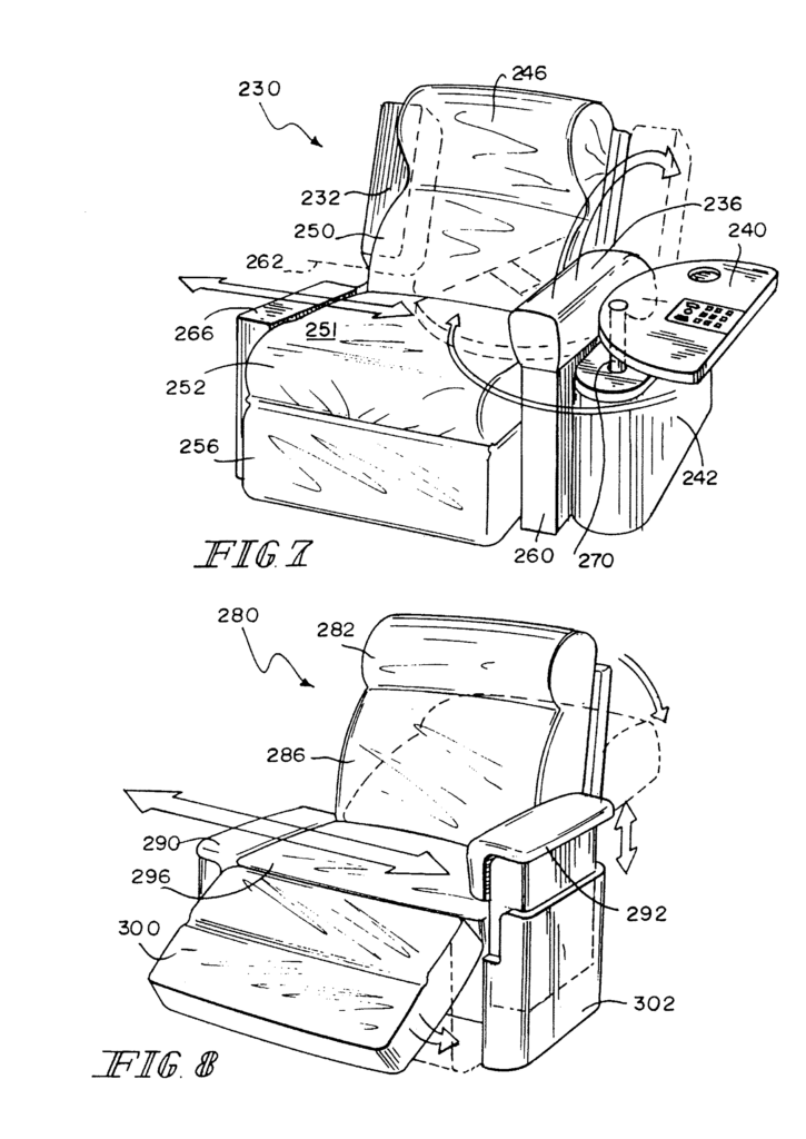
A recliner chair is provided.” The chair is divided into sections for the back, seat and legs. The armrests of the reclining chair are movable. Storage units may be included in some embodiments of the reclining chairs.
Background for Chair with movable arm sections and table sections
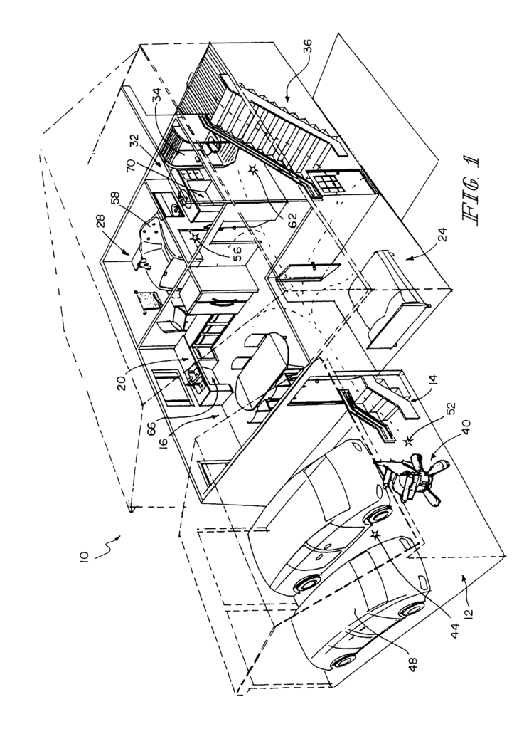
The present disclosure is about personal care and home assistance products. The disclosure includes toileting device, combination bathing-toileting devices, wheelchair accessible bathing appliances, laterally accessible chairs, articulating bed, and a transfer system that includes a personal mobility aid.
Improved health care has resulted in an older population that is highly independent. The elderly population is able to care for themselves with minimal or moderate assistance. The lack of home facilities that accommodate this population’s reduced mobility is a major issue. Toileting, bathing and home furniture are not suitable for people with limited mobility and strength. Different products have been designed to meet specific mobility and assistive needs. However, the integration of these devices across the continuum basic daily activities is still lacking. These basic activities are what define an individual’s independence. This leads to a need for an independent system in the home that provides all basic life activities.
The present invention includes one or more features listed in the claims appended and/or features that, individually or in combination, can constitute patentable subject-matter:
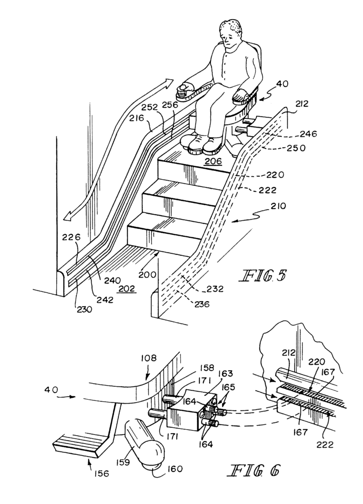
A personal mobility device is included in a system that assists a person with limited mobility to move from one room to another within a house and perform essential daily tasks. The personal mobility system may include a frame with wheels attached to it, a seat mounted on the frame and a driver that allows the device to move up and down stairs. The transfer driver can engage with a guide that is adjacent to the treads of a staircase so that it guides the movement as the device traverses the stairway.
In some embodiments, it is possible for the transfer driver to have teeth that are external and which mesh with the internal teeth of a transfer guide. This will facilitate the movement along the guide of the personal mobility aid. The personal mobility device can include a motor that provides output for driving the transfer driver. The personal mobility device can also include a battery that powers the motor in some embodiments.
The transfer guide may also be movable from a retracted to an extended position. In the extended position, the transfer guide is engaged with the transfer drive. Personal mobility devices may include inputs that control the operation of personal mobility devices, including the operation the transfer driver.
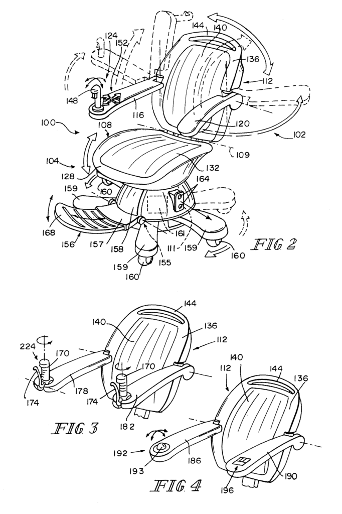
In some embodiments the seat can include a first section with an upwardly-facing surface to support the buttocks and back of a person seated on the seat, and a pivotably attached second portion positioned to support that person’s back. In some embodiments the angle between the two portions may be adjustable. The second portion can be locked in multiple positions relative to first portion, in embodiments where angle between first portion and second portion is adjustable.
In some embodiments the personal mobility device can include an armrest that is attached to the seat. The armrest can be attached to either the first or second portion. In some embodiments the armrest can be pivotable on a horizontal axis. This allows the armrest move from a position of use adjacent to the seat to a position that is out of the way. This allows a person sitting in the seat to enter the seat or exit it by the side. In some embodiments the armrest can be pivotable on a vertical axis. This allows the armrest move from a position of use adjacent to the seat to a position that is out of the way. In other embodiments, an armrest can be pivotable on both horizontal and vertical axes. On the armrests, user input devices can be found. In some embodiments the user input devices can be found on the side of seat.
In some embodiments, an armrest can be attached to the back. It may then be able to pivot about a horizontal plane between a position of use and a position out of the way. In other embodiments, an armrest can be attached to the back. It may then be pivotable around a vertical axis from a position of use to one of out-of-the-way. The armrest can also be attached to the back, and pivotable both about a horizontal axis and a vertical one between a position of use and an out-of the-way position.
In some embodiments, a personal mobility device can be mounted from the rear. A person is supported in an upright position using an integrated support that provides support under their arms. In other embodiments, the person can be seated on the device and supported by a backrest and armrest that runs across the back from one side to another.
In some embodiments, the user inputs for controlling the operation of the mobile device can be attached to the armrest. In some embodiments, the user inputs are located on a side of the seat or an intermediate frame. Users input devices can include joysticks or buttons, twist throttles, squeeze handles, triggers and the like. In certain embodiments, the control of the mobile device can be achieved by using a combination inputs. For example, multiple joysticks and multiple squeeze handles. Pushing a left and right joysticks forward can be a combination input. “Pushing one joystick only forward can cause a turn for example.
The personal mobility device can include a leg that is pivotably attached to the lower frame, and which can pivot around a vertical axis in order to change its position relative to the person seated on the seat. The leg can pivot between two positions where the leg extends lateraly relative to a seat and a position where the leg extends longitudinally relative the seat. The operative width may be reduced in the second position to enable the personal mobility devices to maneuver through narrow passages without interfering home furnishings.
The personal mobility device can include a drivewheel that is attached to the leg. This wheel allows the device to be moved across a surface such as a floor. In certain embodiments, a personal mobility device can include additional non-driven wheel. In other embodiments the personal mobility device can include multiple driven wheels.
In some embodiments the personal mobility device can also include an intermediate support frame that is supported by the lower frame. The seat can be supported by the intermediate frame. The seat can be raised by extending the intermediate frame. The personal mobility aid may also include a footrest that is pivotable around a horizontal axis and coupled to the middle frame. The footrest can be adjusted to change the angle between the footrest and intermediate frame. The footrest can be locked in multiple positions when the angle between footrest and intermediate frame is adjustable.
The transfer guide can include a horizontal first portion that is configured to release or receive the transfer driver. An elevation portion may be coupled to the horizontal first portion to direct the device to another horizontal second portion at a higher elevation than the first portion. This second horizontal section may also be configured to release or receive the transfer driver. In some embodiments the transfer driver can include a plurality vertically-spaced transfer drivers, and the guide can comprise a number of transfer guides configured for receiving or releasing the vertically-spaced transfer drivers. This will maintain the personal mobility devices at a substantially consistent orientation relative to horizontal when transferring from a first to a second height.
In some embodiments, an individual mobility device can include a driveball driven in one direction by a motorized first drivewheel and in another direction by motorized second drivewheel. The first and the second drive wheels can operate simultaneously so that the drive wheel is driven in the resultant direction, based on both the speed and direction of the first drive wheels. “A personal mobility device can include multiple drive wheels coupled to the lower frame and engaged with floor.
In other embodiments, an individual mobility device can be driven by a system of drive wheels that rotate independently. Each drive wheel may have a parallel axis. Each drive wheel can be driven at a speed or direction different from the other to move the personal mobility devices in a desired direction. In some embodiments the axis for rotation of all the drive wheels can intersect the central vertical direction of the personal mobility devices. In some embodiments, the drive wheel axis may be common but distal from a central vertical direction of the device. In some embodiments the personal mobility devices may also include stability wheels that are spaced apart horizontally from drive wheels in order to reduce the risk of tipping. In embodiments in which the drive wheel is distal from the centeral vertical-axis of the device, the stability wheel can be placed opposite to the central vertical-axis to trail the motion of the driving wheels and to vertically stabilize it.
In some embodiments, either the seat or back can be controlled by temperature. The seat, the back or even both can be heated or cooled using a heater. In some embodiments, either the seat or the back of the personal mobile device can massage a person who is supported by the device. In certain embodiments, either the seat or back of the personal mobility device may include an air bladder to support the person supported by the device.
The system to assist a person with limited mobility to move from one room to another within a house and perform essential daily activities includes a powered walker comprising a frame. A plurality drive wheels are coupled to the framework, support handles are coupled to frame and positioned so that a user of the power walker can grip them, and there is a plurality support rollers. The motor may power the drive wheels via a drive linkage that is coupled to the wheels and responds to inputs from the user of the powered walker. The powered walker can be controlled by a person who uses it. They may use the handles to control its speed and direction.
In a first configuration the powered walker can be used as a standard walking device with power assistance. This will reduce the effort required to walk. In a second configuration the powered walker can be converted into a personal mobility aid that allows a person mount an articulable chair on the powered walker, and use the powered wheels to move. The articulable chair may pivot about a horizontal plane from a stowed orientation where the articulable chair is confined within the frame of a powered walker, to a usage position where the articulable is horizontal. The articulable chair may also include a trailing wheels to support the weight of those seated in the seat when the powered walker’s second configuration is used.
The support handles on the powered walker can pivot around a horizontal axis, from a position of support when the powered walker is in its first configuration, to a position of non-support when it is in its second configuration. In the nonsupporting position, the handle may be positioned so that a person seated on the articulable chair can access the controls for the powered walker. The support rollers can be positioned so that they act as foot supports when a powered walker is used in the second configuration.
Click here to view the patent on Google Patents.
Leave a Reply