
Invented by Patrick Foxhoven, John A. Chanak, William FEHRING, Denzil Wessels, Purvi Desai, Manoj Apte, Sudhindra P. Herle, Zscaler Inc
Cloud-based virtual private access systems, also known as VPA, offer a secure and scalable solution for businesses to manage application access. These systems allow users to connect to applications and data stored in the cloud, without the need for a traditional on-premises infrastructure. By leveraging the power of the cloud, businesses can provide their employees with seamless access to applications from anywhere, at any time.
One of the key advantages of cloud-based VPA systems is the enhanced security they offer. Traditional VPNs (Virtual Private Networks) have long been used to secure remote connections, but they can be complex to set up and manage. Cloud-based VPA systems simplify this process by providing a secure connection between the user and the application, without the need for additional hardware or software. This ensures that sensitive data remains protected, even when accessed from outside the corporate network.
Furthermore, cloud-based VPA systems offer scalability and flexibility. As businesses grow and their needs change, these systems can easily accommodate increased demand and additional users. This scalability is particularly important for organizations with a large remote workforce or those that experience seasonal fluctuations in demand. Additionally, cloud-based VPA systems can be easily integrated with existing IT infrastructure, making it easier for businesses to adopt and manage these solutions.
Another key benefit of cloud-based VPA systems is the improved user experience. These systems provide a seamless and consistent user interface, regardless of the device or location from which the application is accessed. This means that employees can work efficiently and effectively, without being hindered by slow or unreliable connections. Additionally, cloud-based VPA systems often include features such as single sign-on and multi-factor authentication, further enhancing the user experience while maintaining security.
The market for cloud-based VPA systems is expected to continue growing in the coming years. According to a report by MarketsandMarkets, the global market for VPA solutions is projected to reach $4.6 billion by 2025, with a compound annual growth rate of 17.4%. This growth can be attributed to the increasing adoption of cloud computing, the rise of remote work, and the need for secure and efficient application access.
In conclusion, the market for cloud-based virtual private access systems and methods for application access is experiencing significant growth. These systems offer businesses a secure, scalable, and flexible solution for managing application access in the cloud. With the increasing demand for remote work and the adoption of cloud computing, cloud-based VPA systems are becoming an essential tool for businesses looking to provide their employees with seamless and secure access to critical applications and data.
The Zscaler Inc invention works as follows
The system and method includes receiving a request from a remote user device in a cloud to access an application. This application may be in a public cloud or private cloud and enterprise network.
Background for Cloud-based virtual private Access Systems and Methods for Application Access
Conventionally, Information Technology (IT) departments and the like see data and computing assets in three possible domains, namely (1) internal networks, (2) private clouds, and (3) public clouds or Software-as-a-Service (SaaS). Users can access internal data through applications such as database programs, etc., when computing moves to cloud. Through a VPN, users can access their documents through a public cloud, such as Microsoft OneDrive or Google Drive. ), etc. It is very difficult for enterprise users to seamlessly connect to applications (?apps?) because of this distribution of computing and data assets. in these domains (without regard to their topology/connectivity/location), and, for the IT administrator, it is difficult to enforce a single, coherent set of policies across these three domains. Enterprise users may be located in branch offices that are not trusted or they can be mobile. Currently, the IT administrator must hairpin end-user traffic to the corporate datacenter via a traditional VPN. (e.g. Secure Sockets Layer or Internet Protocol Security)?and jump to other domains using point-to-point VPNs. The bandwidth of the corporate datacenter is increased linearly for each new branch or nomad user. This increase is not necessary, since most of the VPN traffic inbound will be sent out via a dedicated VPN into the private cloud.
A second option is to install Firewalls and VPN servers in each private cloud, and set up application routing rules so that apps can communicate between domains and multiple private cloud instances. This increases the administrative complexity, and creates additional security vulnerabilities. There is a market need for a “Global VPN” “A cloud-based VPN that maintains a single, secure connection to the cloud and directs traffic to different enterprise assets according to authentication and security policies.
Enterprises, as well as similar entities, deploy private, internally-developed applications that can contain, for instance, personal or financial information, intellectual property and other valuable assets. The applications are a small part of network traffic but contain some of the most important data. VPNs are used to allow remote users access to the network. These solutions can include VPN clients installed on users’ devices, and a VPN termination within the internal network. Site-to-site VPN tunnels may also be used to connect data centers and the cloud as applications migrate to the cloud. Multiple data centers, load balancers, and other technologies are used to increase performance and reachability. This results in higher performance but comes at the cost of maintenance, complexity, scalability, and increased costs. Remote application access, as it is commonly understood, is actually network access from a distance. It has led to major security breaches. A user who only needed access to the application was instead given access to the entire network. VPNs are used to extend the perimeter of the network to include the remote user. This is overkill.
The embodiment includes receiving a request from a remote user device in a cloud to access an applicaiton, wherein that application is located in either a public cloud or a private one, or in an enterprise network. If the user is not allowed to access it, then notifying the device of its absence. This can be done by determining whether a user of the user device has permission to access the application. In order to stitch together the connections, the cloud system can create a connection between the user device as well as the application. This will allow the user device to communicate with the application. At least two tunnels can be created between the user device, and the application. The application can connect to a connector on a computer that is communicatively connected to the cloud system. To access and provide the request, the user device can run a browser or an application. “The determining may include communicating with the central authority in order to determine if the device is allowed and the connection information needed for stitching the connections together.
The method includes: receiving connection information from a central authority in response to an authorized policy check; creating secure tunnels between a user’s device and resources using the connection data. Before the receiving, the user executes the application on the device, authenticates, and sends the request through the application. The application can connect the user’s device to a cloud-based system via a cloud node optimized for the location of the device. The resources can communicate with a lightweight computer connector and be coupled communicatively between the resources, the cloud system and the lightweight connector. The virtual private access can also include detecting resources using a lightweight connector query. The lightweight connector may be blocked from accepting connections from outside the cloud system or enterprise network. To create secure tunnels, one or multiple cloud nodes can be connected in the cloud system. The cloud nodes cannot participate in key exchanges and they do not have access to data on the tunnels. Create secure tunnels by creating connections between cloud nodes. The cloud nodes will create secure tunnels using a combination of client-side certificates and server-side certificates. Secure tunnels can be generated by software on the device and cloud system. A lightweight connector running on a computer connected to the resources is also used.
In another embodiment, the cloud system is adapted to provide virtual private access. It includes one cloud node or multiple cloud nodes that are communicatively connected. Each cloud node has one or several processors, and memory with instructions. When executed, the instructions cause the processors to: receive a request from a remote user device to access resources, which may be located in a public cloud or enterprise network, and where the user device on the Internet is distant from these resources. Forward the request to the central authority to perform a Before the request is received, the user runs an application on their device, authenticates themselves, and then sends the request through the application. The application can connect the user’s device to the cloud-based system via an optimized cloud node, based on the location of the device. The resources can communicate with a lightweight computer connector and be coupled communicatively between them and the cloud system. Memory instructions can be executed to cause one or more processors, based on the query sent to the lightweight connector, to detect resources. It is possible to prevent the lightweight connector from accepting connections from outside the cloud system or enterprise network. Secure tunnels can be built by connecting one or multiple cloud nodes within the cloud system. The cloud nodes must not take part in key exchanges and they cannot access data on the tunnels. Secure tunnels can be built by connecting one or several cloud nodes to the cloud system. The cloud nodes then create secure tunnels using a combination of client-side certificates and server-side certificates. Secure tunnels can be built using software on the device and cloud system. A lightweight connector running on a computer connected to the resources is also used.
The software includes instructions that can be executed by a computer system. This software is stored on a non-transitory medium and contains instructions for the system. These instructions include receiving a request from a device to access resources, where the resources are in either a cloud or enterprise system and the device is located on the Internet. The resources may be coupled with a lightweight computer connector that is communicatively connected between the resources, the cloud system and the lightweight connector.
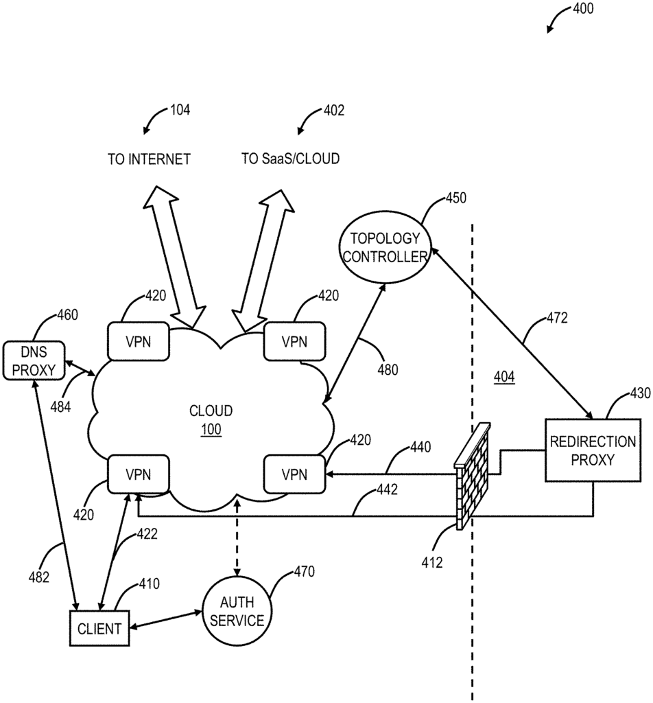
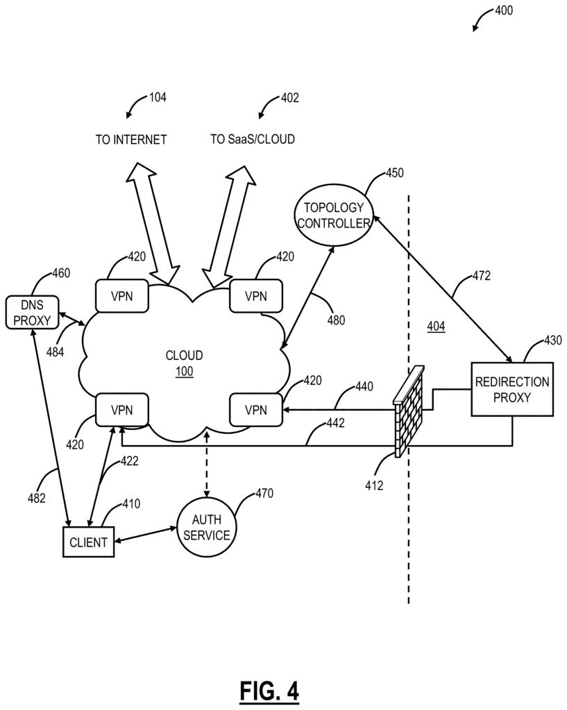
In one embodiment, a method comprises connecting to a VPN device at a cloud-based cloud system, forwarding requests to the VPN device from a client; for requests to an enterprise associated with a client, contacting the topology controller for a topology, causing the VPN device to establish a tunnel from the enterprise and forwarding requests to the cloud-based cloud system for proactive monitoring. The method also includes providing a secure link from the cloud-based cloud system back to an enterprise, including the internal domain and subnet The method may also include authenticating the client via an authentication service prior to connecting, and associating the client with enterprise. After connecting, the method can include setting up a Domain Name Server associated with the cloud to perform DNS lookups on behalf of the client. The method can also include using the DNS to determine the destination of the requests, and for requests destined for the enterprise contacting the topology control to pre-fetch its topology. The method may also include operating an enterprise-based redirection server, which is configured to create a tunnel between the enterprise and the VPN device. The on-premises proxy dials out secure tunnels from the enterprise. On-premises redirection is a virtual server that runs behind the firewall of an enterprise. The on-premises proxy acts as a link between the client’s applications and the enterprise. The VPN device is located on a cloud server in the cloud, where the cloud includes a distributed cloud security. The VPN device may be a software application on a cloud server or a virtual computer on the cloud server. The topology controller contains a network topology for the enterprise, including internal domain names and LAN subnets.
In another embodiment, the cloud system includes one of more Virtual Private Network servers (VPN), wherein one client connects securely to one or multiple VPN servers. A topology controller is communicatively connected to one or several VPN servers. The requests from one or more clients located outside the private network will be forwarded to the cloud-based system without having to traverse the private network. The redirection server maintains a persistent link with the topology controller and creates secure tunnels between the one or multiple VPN servers in response to instructions from the topology controller. The topology control includes the network topology for the private network, including internal domains and subnets. The VPN servers are located on cloud nodes within a distributed security cloud.
In a further embodiment, the VPN system comprises a network interface and data store that are communicatively connected together, as well as a processor. Memory storing instructions will cause the processor to perform the following: establish a secured tunnel with a customer; forward requests received from the client on to the Internet; and, for requests directed to an enterprise contact a topology control to obtain the topology of the company, then cause a VPN to be established between the enterprise and the VPN system; and finally, forward the requests sent by the enterprise via the secure tunnel through the secure tunnel Memory storing instructions which, when executed, cause the processor further to cause the tunnel from the enterprise to be established to the VPN system via an internal redirection proxy.
In various embodiments, methods and systems for cloud-based private virtual access to networked applications have been described. The systems and methods create a connection between three entities dynamically, through a secure tunnel: an endpoint, a cloud and an on-premises proxy redirection. Cloud orchestrates the connection between cloud and on-premises proxy. It is dynamic and on demand. The security of the system and method is a key feature. There is no need for holes to be punched in the on-premises firewall. The redirection proxy within the enterprise (on-premises) “dials out” The cloud is connected to as if it were an endpoint. The ability to dial out on demand and tunnel authenticated traffic to the enterprise, is what makes the systems and methods different.
The paradigm for virtual private access methods and systems is to provide users with network access in order to access an application rather than the entire network. The user shouldn’t be able to access an application if they are not authorized. Virtual private access systems and methodologies provide a new way to deliver secure access. They decouple applications from the network and instead offer access through a lightweight software connecter, which sits in front of applications, an app on the device, and a central authority that pushes policy. A cloud is then used to link the software connectors and applications together on a user-by-application basis.
Users can only view the applications that are allowed in the policy with virtual private access. All other applications are ‘invisible’ All else is ‘invisible? They are ‘dark’ to them. The physical location of an application is no longer relevant, because the virtual private access separates it from the network. If applications are located in multiple places, users will be automatically directed to the instance which provides the best performance. Virtual private access reduces the complexity of configurations such as firewalls and policies in data centers. Businesses can move their applications to Amazon Web Services and Microsoft Azure. They can then take advantage of cloud elasticity, allowing private applications within the enterprise to behave like leading enterprise applications. Virtual private access is not hardware that needs to be purchased or deployed. It is instead a service offered to enterprises and end users.
Example Cloud System Architecture
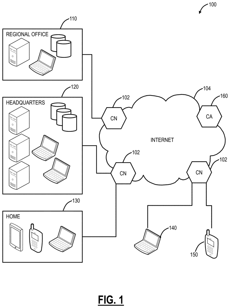
Referring to FIG. In one embodiment, the cloud system 100 shown in FIG. 1 is suitable for use with systems and methods described. Cloud system 100 comprises one or more cloud-nodes (CN) communicatively connected to Internet 104. Cloud nodes 102 can be implemented using a server (as shown in FIG. The cloud nodes 102 may be implemented as a server 200 (as shown in FIG. The cloud system 100 can be a distributed system of security. Cloud nodes 102 allow traffic to be monitored and redirected from different locations, such as regional offices 110, headquarters 120 or employee homes 130. Mobile laptops 140 and mobile devices 150 are also included. Each of the locations 110, 120, 130, 140, 150 are communicatively connected to the Internet 104, and can be monitored through the cloud nodes 102. Cloud system 100 can be configured to perform a variety of functions, such as spam filtering and uniform resource locator filtering (URL filtering), antivirus protection, bandwidth management, data loss prevention, zero day vulnerability protection, web2.0 features, etc. In an embodiment, the cloud system 100 may be viewed as Security-as-a-Service through the cloud. Cloud-based distributed systems that are already in place perform inline processing, where all traffic goes through the cloud to be monitored. DNS is used in the various embodiments of this invention as a less intrusive method for a cloud based distributed security system.
Cloud system 100″ may refer to a cloud-based example security system. Cloud computing methods and systems abstract physical servers, storages, networking etc. Instead, these resources are available on demand and as elastic resources. Cloud computing, according to the National Institute of Standards and Technology, is a model that enables convenient, on demand network access to configurable computing resources, such as networks, servers and storage, and applications and services, which can be quickly provisioned and released without requiring much management or interaction from service providers. Cloud computing is different from the traditional client-server model because it provides applications that are managed and executed by a web browser on a client, without requiring an installed client version. Cloud service providers can centralize their control of browser-based application versions, allowing them to manage licenses and version upgrades on client devices. The phrase ?Software-as-a-Service? SaaS is a term used to describe cloud-based application programs. The cloud is a common term for a cloud computing service, or even an aggregate of all cloud services. “The cloud system 100 illustrated herein is one embodiment of a Cloud-based System, and those with ordinary skill in this art will recognize that the systems and method contemplate operation on any Cloud based system.
Example Server Architecture
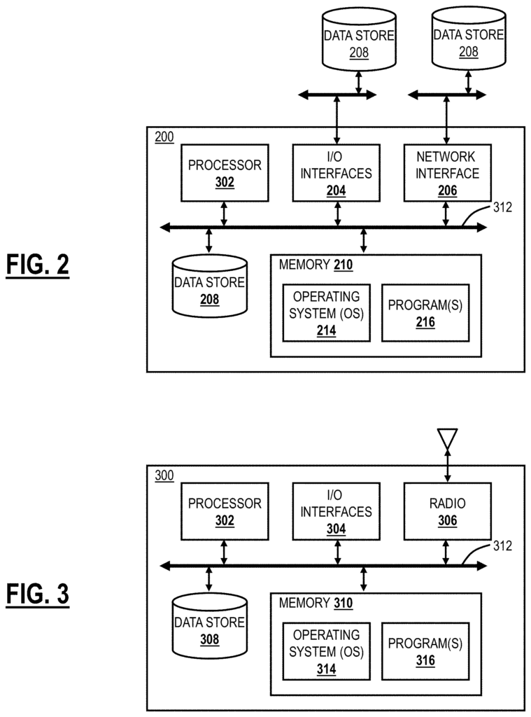
Referring to FIG. In one embodiment, FIG. 2 shows a block diagram of a server 200 that may be used with the system 100 or in other systems. The server 200 can be a digital computing device that includes, in terms hardware architecture, a processor, I/O interfaces, a network, data storage, a memory, and a network interface. It will be understood by those with ordinary skill that FIG. The server 200 is shown in a simplified manner in FIG. 2. A practical embodiment could include additional components or processing logic configured to support conventional operating features, which are not detailed here. Components (202,204,206,208 and 210) are communicatively connected via a local 212. Local interface 212 can be one or more busses or other wired and wireless connections as known in the art. Local interface 212 can have other elements that are not shown for simplicity. These include controllers, drivers, repeaters and receivers. The local interface 212 can also include data, control and/or address connections in order to facilitate appropriate communication among the components.
The processor 202 is an hardware device that executes software instructions. The processor 202 can be a custom-made or commercially-available processor, a central processor (CPU), a auxiliary processor within several processors of the server 200 or a semiconductor microprocessor in the form a chip set or microchip, or any other device that executes software instructions. The processor 202 of the server is designed to run software from the memory, communicate data into and out of the memory, and control the server’s operations according to software instructions. I/O interfaces can be used for receiving user input and/or providing system output from one or more components or devices. Users can input data using a touch pad, keyboard, or mouse. Display device and printer (not depicted) may be used to provide system output. I/O interfaces 204 can include, for instance, a serial or parallel port, a SCSI interface, a Serial ATA interface (SATA), a Fibre Channel, Infiniband, iSCSI interface, a PCI Express (PCI-x) interface, an infrared interface, a RF interface, a PCI Express (PCI) interface and/or a USB interface.
The network interface 206 can be used to allow the server 200 communicate over a network such as the Internet or a local network. The network interface 206 can include an Ethernet card (e.g. 10BaseT or Fast Ethernet), a Gigabit Ethernet or 10 GbE adapter, or a Wireless Local Area Network (WLAN) adapter or card (e.g. 802.11a/b/g/n). The network interface 206 can include address, data, or control connections in order to facilitate appropriate communication on the network. Data can be stored in a data store 208. Data store 208 can include volatile memory elements, nonvolatile elements, or combinations of them. The data store 208 can also include electronic, magnetic or optical storage media. In one example the data store may be internal to the server, such as an internal hard disk connected to the local interfaces 212 of the server. In another embodiment, data store 208 can be external to the server, such as an external hard disk connected to I/O interfaces (e.g. USB or SCSI). In another embodiment, the data storage 208 can be connected to server 200 via a network. For example, it could be a network-attached file server.
Click here to view the patent on Google Patents.
Leave a Reply