
Invented by Freddy Zinger, Omrix Biopharmaceuticals SA
One of the key drivers of this market is the increasing demand for automation and precision in fluid application processes. As industries strive for higher efficiency and productivity, the need for devices that can apply fluids in a controlled manner becomes crucial. These devices ensure consistent and uniform application, reducing wastage and improving overall quality.
In the healthcare sector, fluid applicators play a vital role in medical procedures and treatments. They are used to apply medications, disinfectants, and other fluids during surgeries, wound care, and various diagnostic tests. With the growing emphasis on infection control and patient safety, the demand for advanced fluid applicators with features like adjustable flow rates and sterile disposable components is on the rise.
The automotive industry is another major consumer of fluid applicators. These devices are used in the assembly line for applying adhesives, sealants, and coatings to components and parts. With the increasing complexity of vehicle designs and the need for lightweight materials, the demand for precise and efficient fluid application has surged. Manufacturers are investing in advanced applicators that can handle different viscosities and provide accurate dispensing, ensuring strong bonds and high-quality finishes.
In the construction industry, fluid applicators are used for various purposes, including waterproofing, sealing, and surface coatings. These devices enable contractors to apply fluids in hard-to-reach areas and ensure even coverage, enhancing the durability and longevity of structures. With the growing focus on sustainable construction practices, there is a rising demand for applicators that can handle eco-friendly materials and minimize waste.
The manufacturing sector also relies heavily on fluid applicators for processes such as painting, coating, and lubrication. These devices are used in industries ranging from electronics and appliances to furniture and aerospace. As manufacturers strive for improved product aesthetics and performance, the demand for precise and efficient fluid application systems continues to grow.
In terms of market trends, there is a shift towards the development of smart fluid applicators. These devices are equipped with sensors, actuators, and control systems that enable real-time monitoring and adjustment of fluid flow and pressure. This not only improves accuracy and efficiency but also allows for data collection and analysis, leading to process optimization and cost savings.
Furthermore, there is a growing focus on sustainability and environmental impact in the fluid applicator market. Manufacturers are developing eco-friendly alternatives to traditional fluids, such as water-based paints and biodegradable adhesives. Additionally, efforts are being made to reduce waste generation through improved applicator designs and recycling initiatives.
Overall, the market for devices to apply one or more fluids is thriving due to the increasing demand for automation, precision, and sustainability across various industries. As technology continues to advance, we can expect further innovations in fluid applicators, leading to enhanced efficiency, reduced waste, and improved product quality.
The Omrix Biopharmaceuticals SA invention works as follows
The device to apply one or more fluids, especially a multi-component liquid, such as dental adhesives or medical tissue, consists of a headpiece (9) with channels (25 to 28, for each fluid) extending from the inlet side to the connection site of the piece (9). The tubular body (10) has an inlet facing the connection site on the head piece (9), and an outlet facing away from it. The tubular wall (10) of the tubular (10) body is configured, at least in section, such that it is plastically deformable and particularly bendable.
Background for Device to apply one or more fluids
The application devices mentioned above, are for example known from U.S. Patent No. No. No. These known application devices feed the components from the syringes through channels and discharge them at the device’s discharge site. In certain known application devices these channels extend from a headpiece at the side facing away the syringe body, where a multi lumen tube has been connected. The tube is located at the connection site of the syringe body, towards which the channels (closely adjacent to them) lead. These channels, in turn, begin from the inlet of the syringe bodies facing away from this connection site. On this inlet-side are also the connection devices (cones), which connect the syringe body.
In the application device described in EP 0 315 22 B1, the headpiece is connected to a catheter with four lumens. The catheter has four lumens. Two are used to transport the components of tissue adhesive while the third is for a medical gases. The fourth lumen is filled with a plastically deformable metal wire (shaping cable). Manually bending the tube with multiple lumens simplifies the application of adhesive to certain locations, especially those that are difficult to reach. Metal wires are resistant to axial forces. There is a risk that the tube will not yield immediately if the wire of the shaping tool hits an obstruction in the axial direction. There is also the risk of blocking one of several lumina in the catheter if the metal is bent too much or with an inadequate bending radius.
No. No. No. The application of adhesive to difficult-to-reach sites can be made easier by manually bending the sleeve. The channels that extend through the tube (metal cannulas enclosing the sleeve), are only conditionally pliable when the tubular is hit by an obstacle.
The present invention aims to provide a device that can be used for multiple-component products such as dental or medical adhesives. This device should not suffer from the drawbacks described above and must remain flexible even when it hits obstacles.
The invention provides for a device that applies one or more fluids. This device is particularly suitable for a multi-component liquid such as dental or medical tissue adhesive. It is equipped with a headpiece which has channels for each of the fluids. These channels extend from the inlet side to the connection site.
In the invention, at least the outer wall is plastically deformable and bendable in sections, especially the plastically flexible part of the tubular material. The tubular body is preferably made of plastic and does not have a deflection-resistant configuration. It will therefore give way when it hits obstacles. The application device of this invention has a similar characteristic when a flexible multi-lumen tube is used to transport the components separately from the tubular end. The multiple lumen tubular body is then connected to the headpiece at the connection point, and the tubular surrounds or encloses the tube with more or less tightness or a certain amount of radial clearance. The tubular body’s plastic deformability and bendability is selected so that the elasticity in the multiple lumen tubes does not cause the tubular to automatically reset at the sections of its tubular body deformed by hand.
The device of the invention consists of a tubular body that is at least sectionally plastically flexible, and particularly bendable. It is beneficial to arrange the plastically deformable and non-deformable tubular parts axially. Tubular bodies made from plastic materials with a thin wall thickness (less than 1/10 mm) are particularly bendable in their non-deformable plastic portions. However, this plastic deformation may not be absolute, and can also be elastic. The tubular body, by bending it in the right way, can be shaped into any shape, and can even be returned to its original form.
Advantageously the outer wall is configured to be folded at least sectionally around the body in zigzag fashion, with each folded section consisting of first radially directed inwardly and second radially directed outwardly wall sections. In cross section, the first and second wall sections of the tubular outer wall form a V. The folded section thus resembles a bellows. In contrast to a bellows, the folded section described in this document differs because its first and second walls have different axial dimensions. The first and second walls sections are also connected along a circumferentially extending fold or kinking line. This creates a flexible articulated part in the tubular section. The articulacy is achieved by the individual toggle or over center joints, each formed by the first wall section and one second wall sections connected to it. The first and second walls sections of the tubular section extend saw-toothed in the unbent and axially upset state. When the tubular section is bent, adjacent wall sections move away from one another over a portion of the tubular’s periphery. If the first and second folded section are moved past the “dead centre” when bending, they automatically move to their V-shaped position. The high deflection resistence of the wall sections that extend circumferentially, and in particular the folded sections, is responsible for this automaticity. The way in which the folded section of the tube body described above functions and operates is primarily known from suction and drinking tubules. This invention proposes, for the first time ever, to use such tubular body with articulated configurations for the transfer of components of a dental or medical adhesive as well as for the transfer of medical gases.
The invention provides a feature that allows a tubular tube to be deformed in a plastic manner, allowing fluids to be dispensed locally. The tubular body can be used to receive an elastic catheter with a single lumen or multiple lumens. This is not limited to the tissue adhesive applicator described above, which will be discussed in detail below, but is intended to be used anywhere an elastic deformability is desired.
Alternatively, the tubular device of the invention may consist of deflection resistant rigid tube sections that are articulately connected. The friction between the articulately connected tube sections is selected so that neighboring tube segments do not automatically restore after a pivotal move. Each tube section is advantageously provided with an end that has a partially cylindrical projection which can be clamped in the other end of a neighboring tube. This tube has, at least partially, a similar configuration and encloses this spherical project. The spherical project comprises a hole that is arranged in the axial extension of a tube passage. If tube sections are used of this kind, it is possible to form only a portion of the tube body and configure the remainder of the tube body in a rigid or flexible manner different from the above.
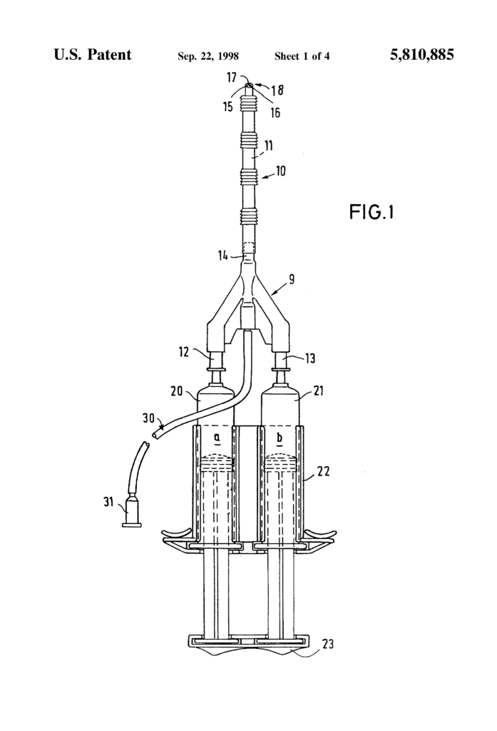
The device for applying two component products such as dental or medical adhesives comprises a flat plastic head piece 9, at the front of which is a tubular tube 10 that receives a multiple lumen tube 11 therethrough. The tubular tube 10 can be attached to either the head piece 9 of the multiple lumen tubes 11. The multiple lumen 11 is partly disposed within the head piece 9. (See inner portion 11a). It has an (outer portion) 11b that protrudes from the tube body 10. The rear end of the tube body 10 is surrounded by the tubular hubs 12, 13. The head piece 9 has a triangular form with rounded edges in top plan view. The multiple lumen tubes 11 protrude through the outer cone 14 on the headpiece body, and their inner portion 11a extends to the area of front half of headpiece. Three lumina 15, 16, and 17 are parallelly arranged from the inner tube end to the discharge end 18 of the multiple lumen tube 11. The lumina 15, 16 and 17 have very thin walls, so they are very close to each other. The tube with multiple lumens can be bent or straightened according to the intended use. The user can shorten the length of the tubular portion 11b and the body 10. The syringes 20 and 21 contain two components, a and b. Their barrels are held together by a rack 22. The syringes 20, 21, are connected by a bridging element 23 so that they can be operated simultaneously. This allows the components a, b to enter the hubs 12 and 13.
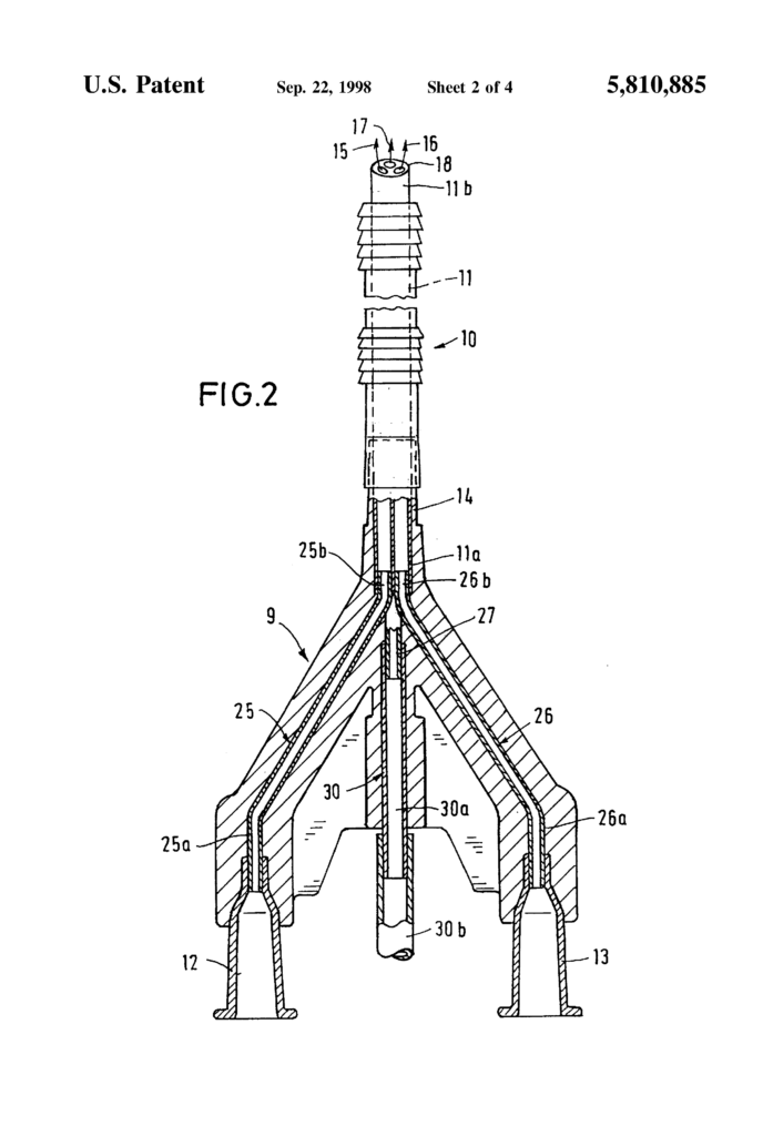
The rigid cannulas 25 and 26, which are preferably metal, are connected to the cannula hubs 12, 13 that are partially included in head piece 9. The metal cannulas 25, 26 are cranked to obtain two legs 25a. 26a. and 25b. 26b. Their axes are parallel, and they are connected with a longer inclined section. The two metal cannulas 25 and 26 are oriented in the head piece 9, so that they extend V-shaped. The cannula hubs 12 and 13 are firmly attached to the rear legs 25, 26a. They extend beyond the edge 9 of the headpiece by a portion of their length. The shorter front legs are 25b and 26b respectively placed into the associated lumens 15, 16 of multiple lumen tube 11, which is provided to conduct the two components separately. A connecting tube 27 is firmly set into the third lumin 17, onto which is attached a flexible soft air tube 30. The connecting tube 27 can be made of plastic or metal. The air tube 30 is a straight line that extends from the tip formed by the metal cannulas 25 and 26 to the rear of the headpiece 9. It has a section 30b which leaves it freely. The portion 30b is 10 cm long. The outer diameter of the tube 30b may be approximately 2.5 mm. A hub-shaped connecting member 31 in the form a hub is provided at the free end of the rear section 30b for connection with an air conduit of an aggregate. The coupling member 31, which may be a female Luer-lock cone, may be used to couple an air filter assembly of the air aggregate.
The metal cannulas 26, 25, the inner portion of the tube with multiple lumens 11, the front portion of the tube 30a, as well as the hubs of the cannulas 12, 13, are moulded into or injected in the plastics material of the head piece 9.
The connecting tube 27 allows the air tube 30 to be in direct contact with the lumen 17, of the multiple lumen tubes 11. As a thin jet, the precise flows of components a and B and the airflow emerge from the discharge end 18, of the multiple lumen tubes 11. Air flow sprays the components a and B in an optimal mix so that the treatment site is supplied with enough dispersed tissue, or dental adhesive. The material is only mixed past the discharge end of the tube 11 due to the separate conductivity of components a and B and air. The syringes 20 and 21 will remain clear, maintaining their original diameters. No obstructions at the discharge end 18 can affect the quality of the product. The adhesive composition is always correct and the exact amounts of components a and B are dosed.
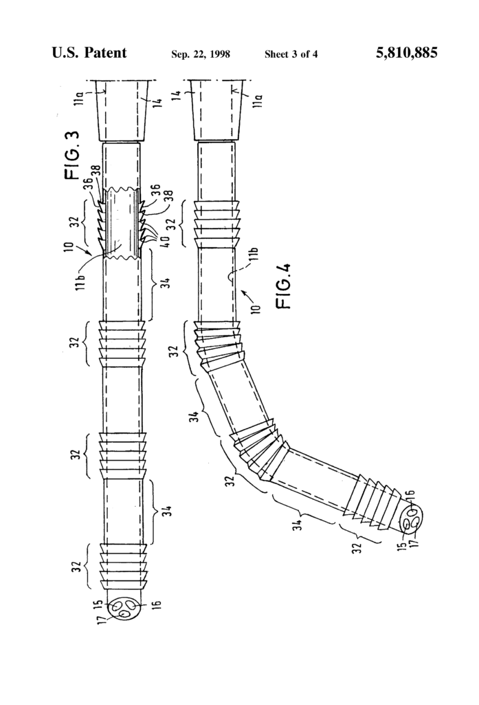
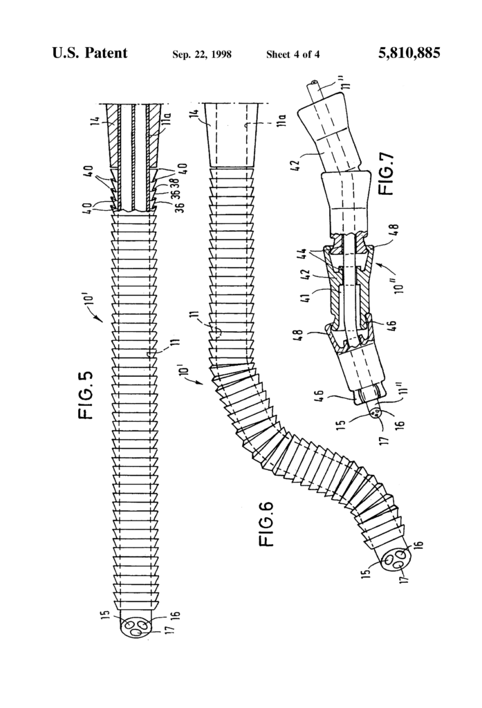
As stated at the start of the description, the multiple lumen tubes 11b are surrounded by a sectionally flexible tubular material 10 made of extruded polymer. According to FIG. According to FIG. The tubular body 10 has a bellows-like configuration in the folded sections 32. It consists of successively arranged first and second wall sections 36 and 38 that extend circumferentially. The wall sections 36 and 38 are alternately arranged and adjacent first and second walls sections 36 and 38 are articulately connected along circumferentially expanding kinking lines or folding regions 40. The first wall sections have a longer axial length than second wall sections. The distance between the two kinking areas 40 that limit a first section of wall 36 is larger than the distance in the case a second section. In FIG. In FIG. 3. The wall sections 36 and 38 are moved away from each other by bending the tube 10 in the region where a folded section 32 occurs. This causes an axial extension to occur in the outer wall. When the wall sections 36 and 38 move away from one another, a radial upsetting occurs in the kinking region 40. The tubular body 10 relaxes when the adjacent wall sections 36,38 move further apart. This results in the curve shown in FIG. The two folded sections 32 are automatically maintained in FIG. 4 (plastic deformability). The neighboring wall sections 36 and 38, without applying any force, cannot return to the state where they abut all around as shown in FIG. This is also associated with a kinking of the tubular section in the kinking region 40 of the folded sections. As described above and illustrated in the figures, the principle of kinkability is well known from drinking and sucking tubules.
FIGS. The tubular body 10′ shown in FIGS. 5 and 6 is an alternative. The tubular 10′ body shown in FIGS. The folded section 32′ of the tubular 10 differs in that it extends the entire length. FIG. FIG. The kinking is partially opposite.
As shown in the FIGURES, the multiple lumen tube 11 can be positioned to follow the desired path. The multiple lumen tube 11, which is shown in FIGS. The tubular body 10 or the 10′ is flexible enough to bend when it hits an obstacle.
FIG. The figure 7 illustrates a modified tubular body 10″, consisting of rigid tube sections 42 with passages 44 aligned in a mutually aligned alignment, through which the catheter 112 extends. Tube sections 42 that are adjacent to one another are connected by ball-and socket joint-like connections. Each tube section 42 has a spherical structure 46 at one end of its axial length. This spherical form is clamped (in a snap-connection-like manner), by the opposite end 48 of each neighboring tube 42.
The catheter 11 \”.” is elastic and prevents the tubular body from returning to its linearly extended state.
It is obvious from the description that it can be modified in many different ways. These variations should not be considered as departing from the spirit or scope of an invention. All modifications that would be obvious to a person skilled in the arts are included within the claims.
Click here to view the patent on Google Patents.
Leave a Reply