Invented by Dinesh Garg, Ramasuri Narayanam, Airbnb Inc
The market for discovering the signature of electronic social networks is a rapidly growing field. This market is driven by the need to understand the behavior of users on social networks, and to identify patterns and trends that can be used to improve marketing strategies, enhance user experience, and prevent cybercrime.
One of the key players in this market is social media analytics companies. These companies use advanced algorithms and machine learning techniques to analyze social media data and provide insights into user behavior. They can track user engagement, sentiment analysis, and even predict future trends based on past data.
Another important player in this market is cybersecurity firms. With the rise of cybercrime, it has become crucial to monitor social networks for any suspicious activity. These firms use advanced tools to detect and prevent cyber attacks, identify fake accounts, and protect user data.
The market for discovering the signature of electronic social networks is also driven by the need for businesses to understand their customers better. By analyzing social media data, companies can gain insights into their customers’ preferences, interests, and behavior. This information can be used to create targeted marketing campaigns, improve customer service, and develop new products and services.
In addition, this market is also driven by the need for governments and law enforcement agencies to monitor social networks for any illegal activity. With the rise of online extremism, hate speech, and terrorism, it has become crucial to monitor social networks for any suspicious activity. This has led to the development of advanced tools and technologies that can detect and prevent such activities.
In conclusion, the market for discovering the signature of electronic social networks is a rapidly growing field that is driven by the need to understand user behavior, prevent cybercrime, and improve marketing strategies. With the rise of social media analytics companies, cybersecurity firms, and advanced tools and technologies, this market is expected to continue to grow in the coming years. As social networks continue to play an increasingly important role in our daily lives, the need to understand their signature will only become more important.

The Airbnb Inc invention works as follows
A method of predicting the behavior in an electronic social network” includes identifying a user’s connections to other users, and creating in a memory a data structure that represents users and their connections within the ESN. The relative importance of a number of electronic communication sources between users is determined by analyzing the data. Each connection between users is assigned a weight. The weight is a value encoded on the basis of a link structure between the users, where the link structure contains metadata that indicates a category and status for the connection. “The probability that a user will communicate with another user is calculated using the data from the plurality of sources. The user’s relationships with other users are then ranked according to the calculated probabilities.
Background for Discovering the signature of electronic social networks
The present inventions are related to systems for social network analysis, and in particular to methods which rank users’ connections within electronic social networks or generate signature graphs based on those ranked connections.
An electronic network of connected users is a virtual community.” Users can establish connections with each other and share information, such as sending messages or publishing announcements, via shared connections. The service provider that hosts a social network can track data such as messages sent between users and/or the link structure in order to gain insights about the network, culture, marketing data and/or user interest. “Networks may have millions and connections of users, and large amounts of data on link structure and activity of users.
According to one embodiment, the method of predicting the behavior in an electronic social network (ESN), includes identifying a user’s connections with others users and creating in a memory a data structure that represents users and their connections within the ESN. The relative importance of a plurality data sources used for electronic communication between users is determined by analyzing the data. Each connection between users is assigned a weight. The weight is an encoded number computed on the basis of a link structure between the users, where the link structure contains metadata that indicates a category and status for each connection. “The probability that a user will communicate with another user is calculated using the data from the plurality of sources. The user’s relationships with other users are then ranked according to the calculated probabilities.
As will be appreciated by those skilled in the art of invention, aspects of the present patents can be embodied in a computer program, a method or a system. Aspects of the inventions can be embodied in a hardware-only embodiment, a software-only embodiment (including resident software, firmware, microcode, etc. ), or combining both. Or an embodiment that combines software and hardware elements, which may be generally referred to as a “circuit,” ?module,? “module,? “Aspects of the inventions can also take the form a computer-readable program product, embodied on one or more computer-readable mediums.
Any combination(s) of one or more computer-readable medium(s), may be used. Computer readable media can be either a computer-readable signal medium, or a storage medium. Computer readable storage media can be an electronic, magnetic or optical system, apparatus or device. It is not limited to these. A non-exhaustive listing of more specific examples of the computer-readable storage medium includes: an electrical connection with one or multiple wires, an optical fiber or cable, a portable computer discette, a hard drive, a random-access memory (RAM), read-only memories (ROM), flash memory or erasable-programmable-read-only memories (EPROMs or Flash memory), or any combination of these. A computer-readable storage medium can be defined as any tangible medium capable of storing a program that is intended to be used by an instruction execution system or apparatus or device.
A computer-readable signal medium can include a propagated signal that contains computer-readable program code, such as in baseband, or as part a carrier wave. This propagated signal can take on a number of different forms, such as electro-magnetic or optical signals, or a combination of both. “A computer-readable signal medium can be any computer-readable medium which is not a computer-readable storage medium, and which can communicate, transmit, or transport a programme for use by, or in conjunction with, an instruction execution system or apparatus or device.
Program code embedded on a computer-readable medium can be transmitted by any appropriate medium including, but not limited, to wireless, wireline transmission, optical fiber cable, radio frequency, etc. or any combination suitable of the above.
The computer program code that carries out the operations of the inventions can be written in any combination or languages. This includes object-oriented languages such as Java, Smalltalk or C++ and procedural languages such as?C? The programming language, or languages similar to it, can be used. The code can be executed on a user’s PC, on a remote server, or on both. The remote computer can be connected to the computer of the user through any network type, such as a LAN or WAN, or it may connect to an external computer, for example through an Internet Service Provider.
The following sections describe aspects of the inventions with flowchart illustrations or block diagrams that show methods, apparatuses (systems), and computer programs according to the embodiments. Each block in the flowchart diagrams and/or illustrations, as well as combinations of blocks, can be implemented using computer program instructions. These computer program instructions can be given to a processor in a general-purpose computer, special-purpose computer, or another programmable device to create a machine. The instructions are then executed by the processor to produce the machine.
The computer program instructions can also be stored on a computer-readable medium. This computer-readable medium can direct a computer or other programmable data processor apparatus to perform in a certain manner.
The computer program instructions can also be loaded on a computer, another programmable data processor, or any other device to perform a series operational steps on the computer, the other programmable device, or the other devices in order to produce a “computer implemented process” such that the instructions which execute on the computers or other programmable devices provide processes to implement the functions/acts specified on the flowchart or block diagram block or block.
Referring to the figures, and particularly to FIGS. In Figures 1 and 2, we show illustrative diagrams of data-processing environments in which the illustrative embodiments can be implemented. Please note that FIGS. The environments in which the different embodiments can be implemented are not limited by FIGS. The depicted environments can be modified in many ways.
The flowcharts, block diagrams, and other figures are intended to illustrate the architecture, functionality and operation of various implementations of computer programs, systems, and methods according to different embodiments of this invention. Each block in flowcharts and block diagrams can be interpreted as a module, segment or portion of code that contains one or more executables instructions to implement the specified logical functions. In some alternative implementations the functions listed in the block could occur in a different order than the one shown in the figure. As an example, two successive blocks can be executed simultaneously or in reverse order depending on the functionality. “It will be noted as well that each block in the flowchart and/or block diagram illustrations, as well combinations of blocks, can be implemented using special-purpose hardware systems that perform specified functions or actions, or combinations special purpose hardware with computer instructions.
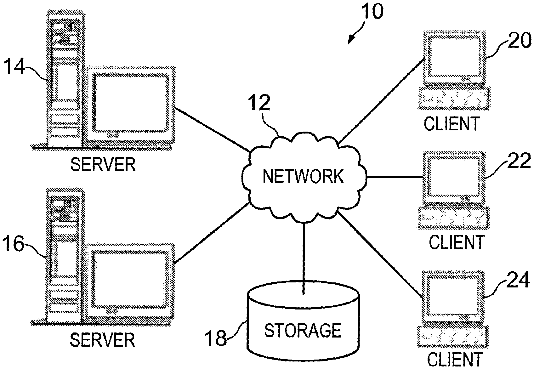
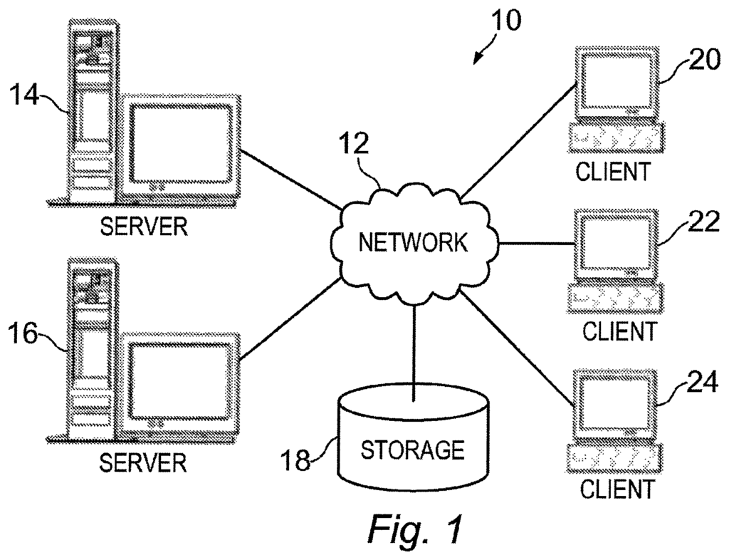
FIG. The pictorial representation 1 shows a computer system 10, which includes a network that may implement illustrative implementations. Computer system 10 can include a network 12 which is a medium for providing communications links between devices and computers within computer system 10. The network 12 can include wires, wireless communication links or fiber optic cables or combinations thereof.
In the example shown, a network 12 may be connected by a server 14, a second server 16, and a storage unit 18. One or more client computers can also connect to the network 12. For example, a first computer client 20, a second computer client 22, and a final computer client 24. Client computers 20, 22 and 24 can be personal computers, workstations, or network computers. Server 14 can provide data to client computers 20, 22 and 24 in the example shown. This includes boot files, operating systems images and/or software applications. In this example, client computers 20, 22 and 24 are servers to server 14. “Computer system 10 can include additional clients, servers and other devices that are not shown or include fewer devices.
In the illustrated example, network 12 can be or include the Internet. The computer system 10 may also be implemented using a variety of different networks, including an intranet or a local network. FIG. “Figure 1 is meant as an example and not an architectural restriction for the various illustrative manifestations.
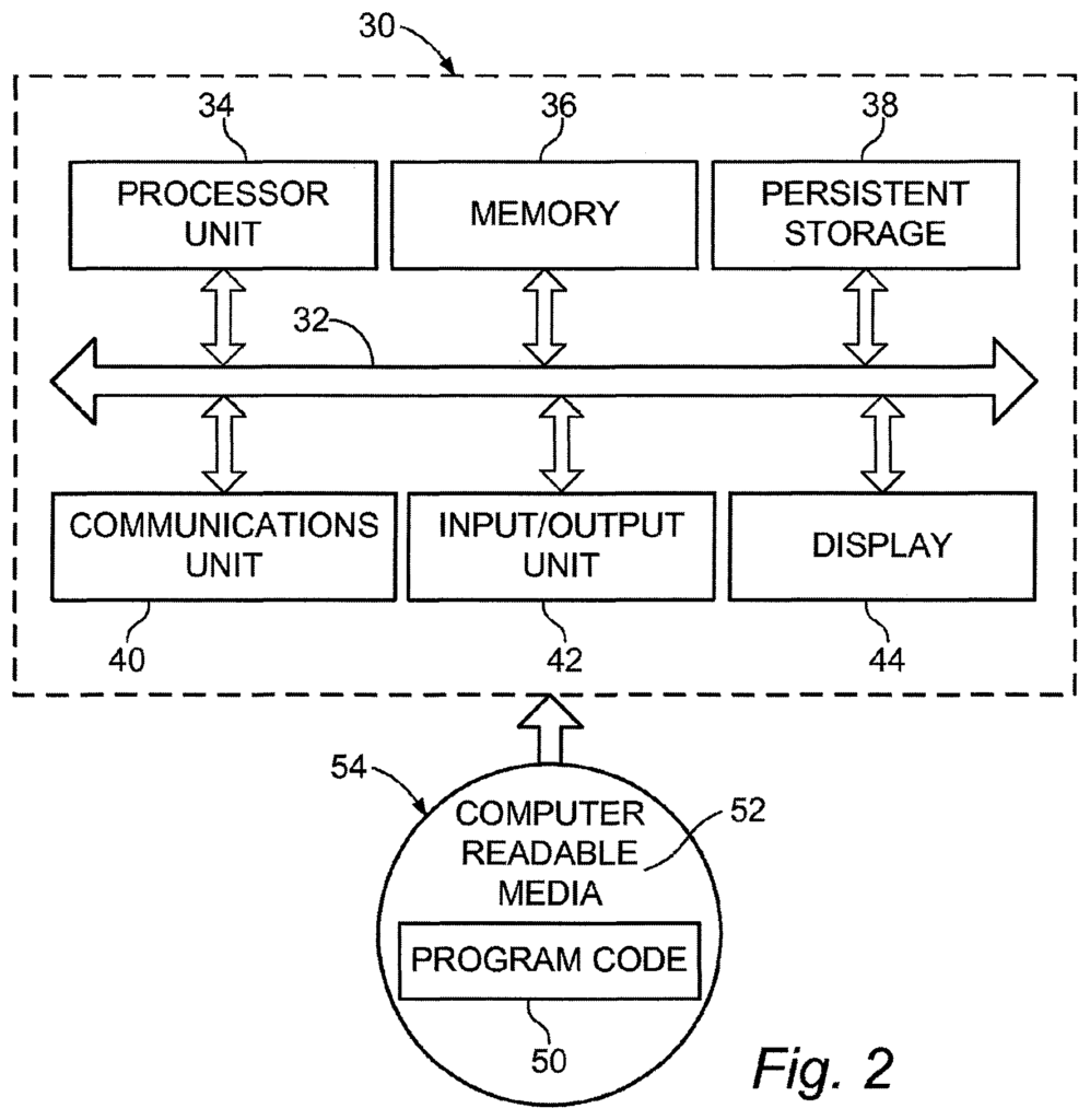
Referring to FIG. In FIG. 2, a block-diagram of a data processing system 30 illustrating illustrative implementations is shown. Data processing system 30, for example, is a computer such as the server 14 or client 20 shown in FIG. In the illustrated embodiments, computer-usable code or instructions for implementing processes can be found in FIG. In this example, the data processing system 30 includes communications fabric 32 that provides communication between a processor 34, a memory, a persistent store 38, a communications module 40, and an input/output unit 42. Other examples of a data-processing system can include more or less devices.
Processor Unit 34″, also known as simply a processor or a CPU, can be used to execute software instructions that are loaded from persistent storage into memory 36. The processor unit 34 can be made up of a group of one or multiple processors, or it could be a multiprocessor core depending on how the implementation is done. Processor unit 34 can also be implemented with one or more heterogeneous systems, where a primary processor and secondary processors are on the same chip. Another example of a processor unit 34 is a multi-processor symmetric system that contains multiple processors with the same type.
Storage devices include memory 36 and persistent storage. Storage devices are any hardware capable of storing data on a temporary or permanent basis. In these examples, memory 36 can be a random-access memory, or any other non-volatile or volatile storage device. Persistent Storage 38 can take on different forms, depending on how it is implemented. Persistent storage 38, for example, may include one or more devices or components. As an example, persistent storage 28 may be a disk drive, flash memory, optical disk, magnetic tape or a combination thereof. Media used for persistent storage 38 may also be removable. “Persistent storage 38 can be implemented using removable hard drives.
In these examples, “Communications Unit 40” provides communications with other devices or data processing systems. Communications unit 40 could be, for example, a network card. The communications unit 40 can provide communication using both wireless and physical communications links.
![]()
Input/output Unit 42″ allows data to be inputted and outputted with other devices connected to the data processing system 30. Input/output 42, for example, may allow user input via a keyboard or mouse. Input/output 42 can also send output to a print device. Display 44 shows information to the user.
Click here to view the patent on Google Patents.
Leave a Reply