Invented by Aly E. Orady, Michael Valente, Darryl Weatherspoon, Bret G. Stott, Tonal Systems Inc
One of the key features of these exercise machines is the lockable mount. This allows users to securely attach their exercise equipment to the machine, ensuring stability and safety during workouts. Whether it’s a stationary bike, rowing machine, or weight bench, the lockable mount keeps the equipment in place, preventing any wobbling or movement that could lead to accidents or injuries.
The translatable mount is another important feature that sets these exercise machines apart. It allows users to easily adjust the position of the equipment, accommodating different body types and workout preferences. This versatility is particularly beneficial for multi-user environments, such as gyms or fitness studios, where individuals of varying heights and sizes may be using the same machine.
The market for exercise machines with lockable and translatable mounts caters to a wide range of fitness enthusiasts. From beginners looking to start their fitness journey to experienced athletes seeking to enhance their performance, these machines offer something for everyone. The lockable mount ensures stability and safety, allowing users to focus on their workouts without worrying about equipment movement or accidents.
Furthermore, the translatable mount feature allows users to customize their workout experience. Whether it’s adjusting the seat height on a stationary bike or changing the incline on a weight bench, individuals can tailor the equipment to their specific needs and fitness goals. This adaptability not only enhances the effectiveness of the workout but also promotes user comfort and satisfaction.
In addition to the benefits for individual users, exercise machines with lockable and translatable mounts also offer advantages for gym owners and fitness professionals. The lockable mount ensures that equipment stays in place, reducing the risk of damage and prolonging the lifespan of the machines. The translatable mount feature allows for easy equipment reconfiguration, enabling gym owners to optimize their space and accommodate a variety of workout routines.
As the demand for home fitness equipment continues to rise, exercise machines with lockable and translatable mounts have become a popular choice for individuals looking to create their own personal gym space. These machines offer the convenience of a gym workout without the need to leave the comfort of home. The lockable mount ensures stability and safety, while the translatable mount allows for easy customization to fit any space or workout routine.
In conclusion, the market for exercise machines with lockable and translatable mounts has experienced significant growth due to their numerous benefits for fitness enthusiasts. These machines offer stability, safety, and versatility, making them an attractive option for both home and commercial gyms. With the increasing demand for home fitness equipment, these innovative machines are likely to continue gaining popularity in the years to come.

The Tonal Systems Inc invention works as follows
An exercise device comprises a motor.” Exercise machine with lockable mount. The cable is connected to the motor by the lockable mount. The lockable translatable mounting is coupled with a sensor. The sensor is at least partially used to determine the mount lock status.
Background for Exercise machine with lockable and translatable mount
Strength training is also known as resistance training or lifting weights. It’s an important part of every exercise program. It helps to build muscle, burn fat and improve a variety of metabolic factors, including insulin sensitivity, lipid levels and elasticity. “Many users are looking for a safer and more effective method of strength training.
The invention may be implemented in many ways. It can be used as an apparatus, a process, a system, a composition, a product of computer programming, and/or a CPU, such as one that executes instructions stored on or provided by a memory connected to the processor. These implementations and any other form of the invention can be called techniques in this specification. The invention allows for the possibility of altering the order of steps in disclosed processes. A component, such as a processor and a memory, described as being capable of performing a task can be implemented either as a general component that is temporarily set up to perform the task at a particular time or as a specific component that was manufactured to do the task. The term “processor” is used herein. The term “processor” refers to any one or more devices, circuits and/or processing cores that are designed to process data such as computer program instruction.
Below is a detailed description of some embodiments of the invention, along with accompanying figures that illustrate its principles. Although the invention is described with these embodiments in mind, it is not limited to them. The claims limit the scope of the invention, and the invention includes many alternatives, modifications, and equivalents. The following description provides a detailed understanding of the invention. These details are given for example purposes only. The invention can be used according to the claims without any or all of these details. To be clear, the technical material related to the invention that is well-known has not been described in detail. This is done in order not to obscure the invention.
The majority of strength-training methods and/or equipment fall into one or more of the following categories.
While gravity is the primary source for tension or resistance, tension can also be achieved by using elastics such as rubber bands/resistance band as with THERABAND. Other methods include pneumatics and hydraulics. These systems are characterized by their own tension curve.
Electronic Resistance.
Patent application Ser. No. No. 20. 2017, which is incorporated by reference herein for all purposes. Electronic resistance can be generated by an electromagnetic field, an electronic motor, or a brushless direct current (BLDC) three-phase motor. The techniques discussed in the present application can be applied to any other traditional exercise machine without restriction, such as exercise machines that use pneumatic cylinders or springs.
Low Profile.
A strength-trainer using electricity to create tension/resistance can be smaller and lighter than conventional strength-training systems, such as a stack of weights, and therefore, it may be installed or mounted at more places, for example, the wall of a room in a residential house. Low-profile systems and components will be preferred for this type of strength trainer. Strength trainers that use electricity to create tension/resistance can also be made versatile through electronic or digital control. Software can be used to control tension with electronic control. Traditional systems, on the other hand, require that tension be manually/physically changed. In the case of weight stacks, a pin must be moved from one metal plate onto another by a user.
The digital strength trainer that uses electricity to create tension/resistance can also be versatile, as it has dynamic resistance. This allows tension/resistance to be changed almost instantly. Digital strength trainers can apply tension curves based on the position of the user and their range of movement. This includes both the phase and the position. The shape of the curves can be altered continuously or in response to an event. Tension may also be controlled in real-time based on internal and external variables, including phase and position.
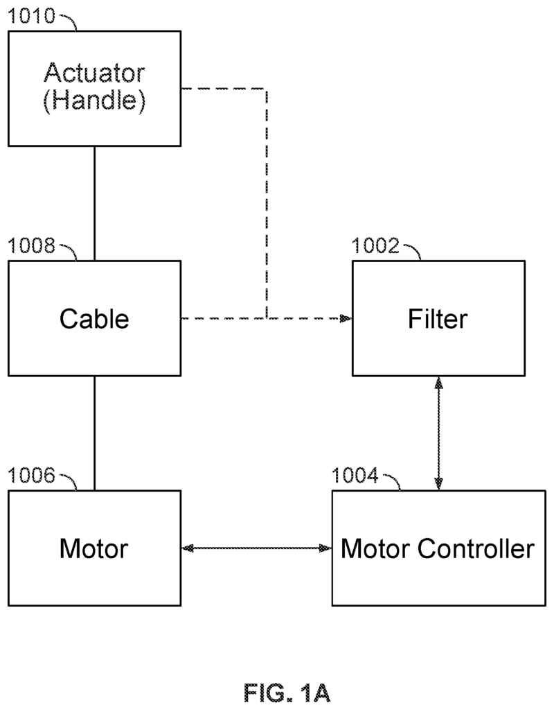
FIG. “FIG. 1A is a diagram showing an embodiment of a machine for exercising. “The exercise machine includes:
a controller circuit (1004), which may include a processor, inverter, pulse-width-modulator, and/or a Variable Frequency Drive (VFD);
a motor (1006), such as a brushless DC three-phase motor driven by the control circuit;
A spool wrapped with a cable (1008) and coupled to it. The cable is connected to an actuator/handle (1010) so that the user can grip and pull. The spool is coupled to the motor (1006) either directly or via a shaft/belt/chain/gear mechanism. In this specification, the spool is also called a “hub”. ;
A filter (1002) to digitally control controller circuit (1004) based on information received from the cable (1008 and/or actuator (10010)
Optionally (not shown on FIG. 1A) A gearbox is placed between the motor and the spool. Gearboxes can multiply torque or friction, divide speed and/or split the power between multiple spools. A number of combinations of motors and gearboxes can be used without changing the fundamentals for digital strength training. “A cable-pulley system can be used instead of a motor, or a dual motor can be used instead of a transmission;
1A): “one or more sensors” 1A):
A position encoder, a sensor that measures the position of the motor (1010) or actuator (1010). Position encoders can include hall effect shaft encoders, grey-code encoders on motors/spools/cables (1008), accelerometers in actuators/handles (1010), optical sensors or position measurement sensors/methods integrated directly into motors (1006). In one embodiment, a low-resolution encoder is associated with a phase encoder that uses an optical encoder with a pattern of encoding. There are also other options which measure the back-EMF from the motor (1006) in order to calculate location.
a motor power sensors; a sensor that measures voltage and/or the current consumed by the motor (1006);
a user tension sensor; a torque/tension/strain sensor and/or gauge to measure how much tension/force is being applied to the actuator (1010) by the user. In one embodiment, the tension sensor is integrated into the cable (1008). A strain gauge can also be built into the motor mount that holds the motor (1006). The strain that is created by the user pulling on the actuator (1010) can be measured with a Wheatstone Bridge strain gauge. In another embodiment, a cable (1008) can be guided through a pulledey that is coupled to a cell of load. In another embodiment, the belt that connects the motor (1006) with cable spool (1008) or gearbox (1008) is guided through a pulledey coupled to a cell. In another embodiment, resistance generated by motor (1006) can be characterized according to voltage, current or frequency inputted into the motor.
In one embodiment, the three-phase brushless DC (1006) motor is used in conjunction with:
Click here to view the patent on Google Patents.
Leave a Reply