
Invented by Min SHENG, Fontem Holdings 1 BV
Electronic cigarettes, also known as e-cigarettes or vapes, have gained immense popularity over the past decade. As the demand for these devices continues to rise, so does the need for liquid containers, commonly referred to as vape tanks or cartridges. These containers hold the e-liquid, which is vaporized and inhaled by the user. The market for liquid containers for electronic cigarettes has witnessed significant growth, driven by various factors such as technological advancements, changing consumer preferences, and increasing awareness about the harmful effects of traditional smoking.
One of the key drivers of the market is the constant innovation and technological advancements in the vaping industry. Manufacturers are continuously developing new and improved liquid containers to enhance the vaping experience. These containers are designed to deliver better flavor, increased vapor production, and longer-lasting performance. Companies are investing in research and development to create leak-proof and user-friendly designs, ensuring a hassle-free vaping experience for consumers.
Another factor contributing to the growth of the market is the changing consumer preferences. Many smokers are transitioning to e-cigarettes as a healthier alternative to traditional tobacco smoking. This shift has created a demand for a wide range of e-liquid flavors and nicotine strengths, leading to a diverse market for liquid containers. Manufacturers are catering to this demand by offering a variety of tank sizes and designs to accommodate different e-liquid preferences.
Furthermore, the increasing awareness about the harmful effects of smoking has prompted governments and health organizations to promote vaping as a less harmful alternative. This has resulted in a surge in the number of people turning to e-cigarettes, thereby driving the demand for liquid containers. Additionally, the availability of e-cigarettes in various retail channels, including convenience stores, online platforms, and specialty vape shops, has further contributed to the market growth.
The market for liquid containers for electronic cigarettes is highly competitive, with numerous players vying for market share. Established companies, as well as new entrants, are constantly introducing innovative products to gain a competitive edge. Manufacturers are focusing on product differentiation through features such as adjustable airflow, top-fill systems, and compatibility with different types of coils. Additionally, branding and packaging play a crucial role in attracting consumers, with companies investing in eye-catching designs and appealing marketing strategies.
However, the market also faces challenges, primarily related to regulations and safety concerns. Governments across the globe are implementing strict regulations on the manufacturing, sale, and advertising of e-cigarettes. These regulations aim to ensure product safety, prevent underage vaping, and restrict the marketing of e-cigarettes to non-smokers. Compliance with these regulations can be costly for manufacturers, impacting the overall market growth.
In conclusion, the market for liquid containers for electronic cigarettes is witnessing significant growth due to various factors such as technological advancements, changing consumer preferences, and increasing awareness about the harmful effects of traditional smoking. Manufacturers are continuously innovating to meet the demand for better performance, flavors, and convenience. However, regulatory challenges pose a potential hurdle for the market’s expansion. As the vaping industry continues to evolve, the market for liquid containers is expected to thrive, catering to the growing number of e-cigarette users worldwide.
The Fontem Holdings 1 BV invention works as follows
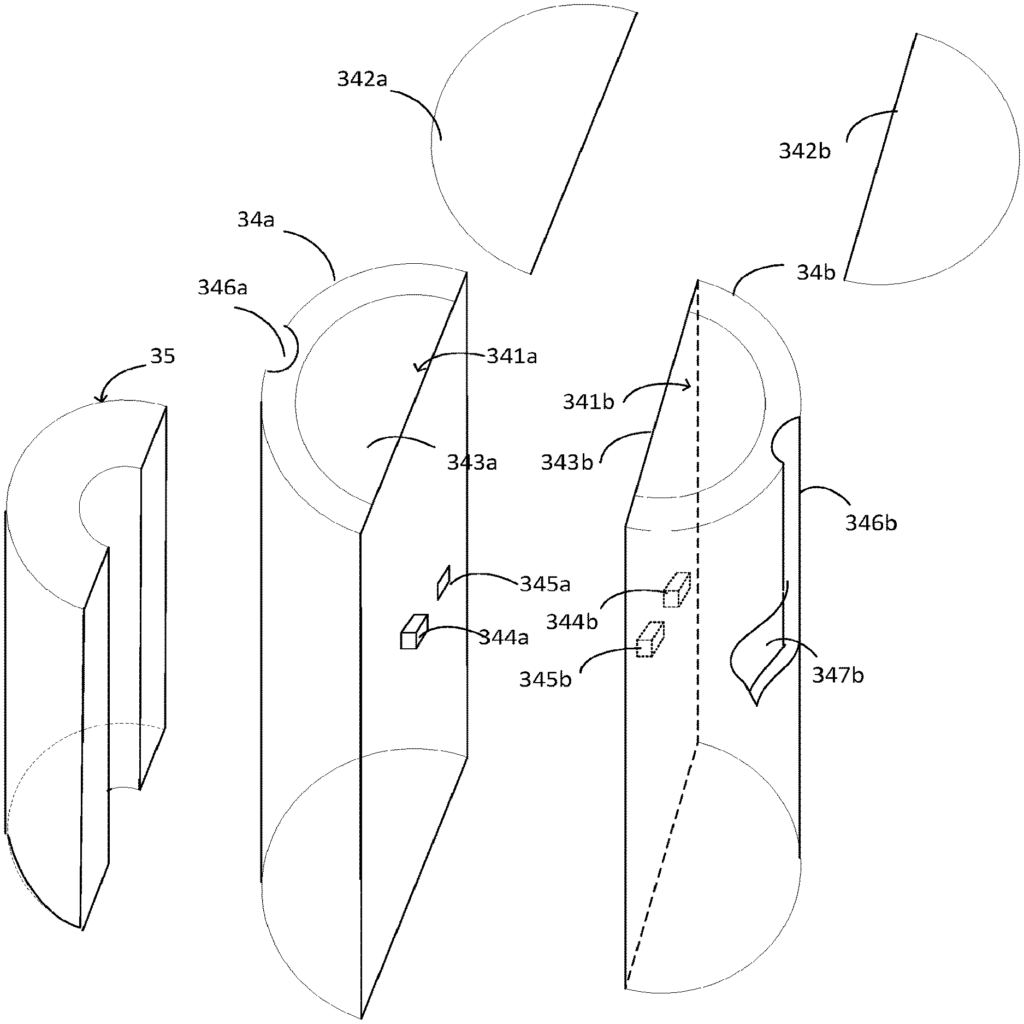
An electronic smoke device comprises a liquid source (34) and an Atomizer in a housing. The liquid supply (34) consists of at least two container member (34a,34b) that can be connected to each other through a connection device to form the liquid supply main body. “Each of the container member (34a) can have an outlet (341a or 341b), sealed by a seal (342a or 342b), and a second closed end, as well as an aerosol channel formed between the two container members.
Background for Liquid containers for electronic cigarettes
Many electronic smoking and vaporizing devices have an open tank system that allows the user to refill the tank. Open tank systems, however, allow for any liquid to fill the tank, which can have some disadvantages. It is better to avoid refilling as it increases the risk of liquid contact with the user’s hands. Some electronic vaporizing systems use a sealed system. The device may not be refillable or it can only be refilled using a container that is closed. Closed systems have many advantages over open systems. However, it is still difficult to design liquid containers that are convenient and easy to use, as well as allowing for the simultaneous use of multiple liquids.
An electronic smoke device comprises a liquid source and an atomizer within a housing.” The liquid supply comprises at least two container member that can be connected to each other through a connection system to form the main body of the liquid supply. “Each of the container member may have a sealed first end and a closed second end, with an aerosol channel between the container members.
Electronic Cigarettes as a Whole
As shown in FIG. A typical e-cigarette 10, which has an electronic cigarette housing, is a cylindrical tube with an end cap. The hollow cylindrical tube can be a single-piece tube or multiple-piece tube. In FIG. In FIG. Together, the battery portion 12 with the atomizer/liquid-reservoir portion 14 form a cylindrical hollow tube that is about the same size and shape of a conventional cigarette. Typically, the diameter is 7.5 mm. However, the length may vary from 70 to 180 mm and the diameter can range from 5-20 mm.
The battery 12 and atomizer/liquid-reservoir portion 14 are usually made of plastic or metal and work together with the end cap to form a housing that contains the components of an ecigarette 10. The battery portion 12 may be designed to snap together, by bayonet attachment or magnetic fit. The battery portion 12 includes an end cap 16. It is located at the front of the battery 12. The end cap 16 can be made of translucent plastic or another translucent material, allowing an LED 20 located near the cap to emit light.
An air intake may be provided at the end cap or anywhere along the length the cylindrical hollow tubes, or at any connection between the battery portion 12 (and the atomizer/liquid-reservoir portion 14). FIG. FIG.
The cylindrical hollow tube portion 12 contains “a battery 18, a light-emitting diode 20, control electronics 22, and optionally an Airflow Sensor 24. The control electronics 22 is electrically linked to the LED 20, and to the airflow sensors 24. The LED 20 is located at the front of the battery 12 portion, adjacent to the cap 16. The control electronics 22 as well as the airflow sensor 24 can be found at the opposite end of battery 12.
The airflow detector 24 acts as a suck or puff detector. It detects a user sucking or suckling on the atomizer/liquid-reservoir portion 14 of the electronic cigarette 10. The airflow sensors 24 can be any sensor that detects changes in airflow, air pressure or both. For example, a microphone switch with a membrane deformable by air pressure variations. The sensor can also be an electronic sensor or a Hall sensor.
The control electronics 22 is also connected to a atomizer. In the example shown the atomizer includes a heating element 28 that is wrapped around a wick 30, which extends across the central passage 32 in the atomizer/liquid-reservoir portion 14. The coil 28 can be placed anywhere within the atomizer, and it may be either transverse or parallel with the liquid reservoir. The central passage 32 is not blocked by the wick 30 or heating coil 28. Instead, an air gap on either side is provided to allow air to pass past the heating element 28 and the wick. Other heating elements can be used in the atomizer, including ceramic heaters or heaters made of fibers or mesh. In the atomizer, non-resistance elements like sonics, piezos and jet sprays can be used instead of the heating coil.
The wick 30 may be a porous material such as a bundle of fiberglass fibers, with liquid in the liquid supply 33 drawn by capillary action from the ends. The wick 30, which may be made of porous materials such as fiberglass fibers, draws liquid from the liquid supply 33 by capillary force.
The liquid supply 33 can also include wadding that is soaked in a liquid and which surrounds the central passage 32, with the ends 30 of the wick abutting it. Other embodiments of the liquid supply 33 can include a toroidal chamber arranged to fill with liquid, with the ends 30 extending into it.
At the rear end of the atomizer/liquid-reservoir portion 14, there is an air inhalation hole 36. Inhalation port 36 can be located in the hollow cylindrical tube of the atomizer/liquid storage portion 14. It may also be found in a separate, attached mouthpiece.
When used, the user sucking on the ecigarette 10 The air is drawn in through one or more air intakes, like air inlets 38, and drawn along the central passage 32 to the air inhalation ports 36. Airflow sensor 24 detects the change in air pressure and generates a signal which is sent to control electronics 22. The control electronics 22 responds to the signal by activating the heating coil 28, which vaporizes liquid in the wick 30, creating an aerosol within the central passage. This aerosol may contain both liquid and gas components. The aerosol created by the ecigarette 10 is inhaled as the user continues sucking on it. The control electronics 22 activates the LED 20, which lights up and is visible through the translucent end cap 16, simulating a glowing ember on the end of conventional cigarettes. “As liquid in the wick is converted to an aerosol, more liquid from the liquid supply is drawn into wick 30 by capillary effect and is then available for conversion into aerosol via subsequent activation of heating coil 28.
Some ecigarettes are disposable. The electric power of the battery 18 should be enough to vaporize liquid in the liquid supply, after which the ecigarette 10 will be thrown out. In some embodiments, the battery 18 can be recharged and the liquid supply can be refilled. If the liquid reservoir 33 is a cavity toroidal, it can be refilled via a port. In some embodiments, the atomizer/liquid-reservoir portion 14 is removable from the battery portion 12, and a replacement atomizer/liquid-reservoir portion 14 can then be fitted with a liquid supply 33 to replenish the liquid supply. “In some cases, replacing liquid supply 33 can include replacement of both the heating coil 28 as well as the wick 30, along with the replacement.
The new liquid supply 33 can be in the shape of a cartridge with a central passage through which an aerosol is inhaled by the user. In some embodiments, the aerosol can flow from the cartridge’s exterior to the air inhalation ports 36.
Ofcourse, variations exist in addition to this description of the structure of function of an e-cigarette 10. The LED 20 can be removed, for example. The airflow sensors 24 can be located next to the end cap 16, rather than in middle of the electronic cigarette. The airflow sensors 24 can be replaced by a switch that allows the user to manually activate the ecigarette rather than responding to a change in the air pressure or flow.
Different types of atomizers can be used. The atomizer could, for instance, have a heating element in a cavity within a porous material soaked in liquid. This design produces aerosol by evaporating liquid in the porous material either by activating the coil heating it or by passing heated air over or through it. The atomizer can also use a piezoelectric heater to create aerosols, either in conjunction or without a heater.
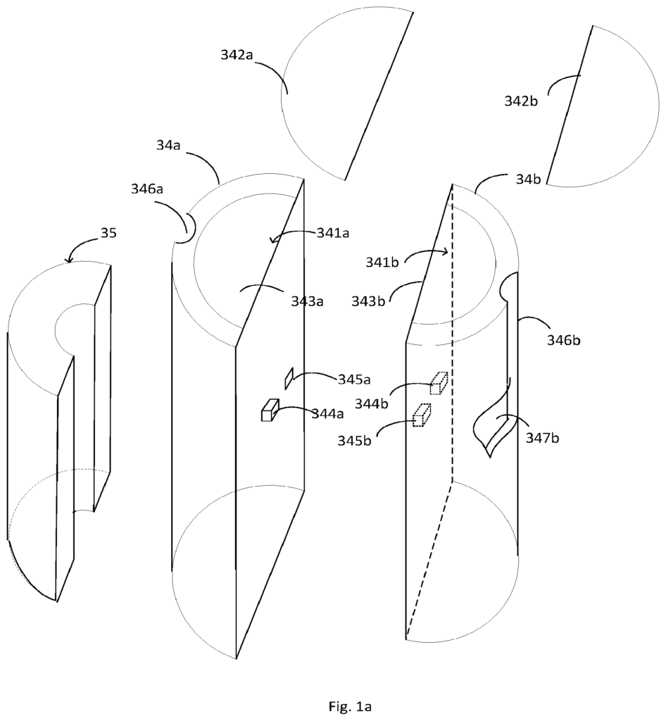
A liquid supply 34 for electronic smoking devices has been disclosed. The liquid supply 34 is composed of a first container 34 a, and a complementary second container 34 b to form a substantially cylinder body.
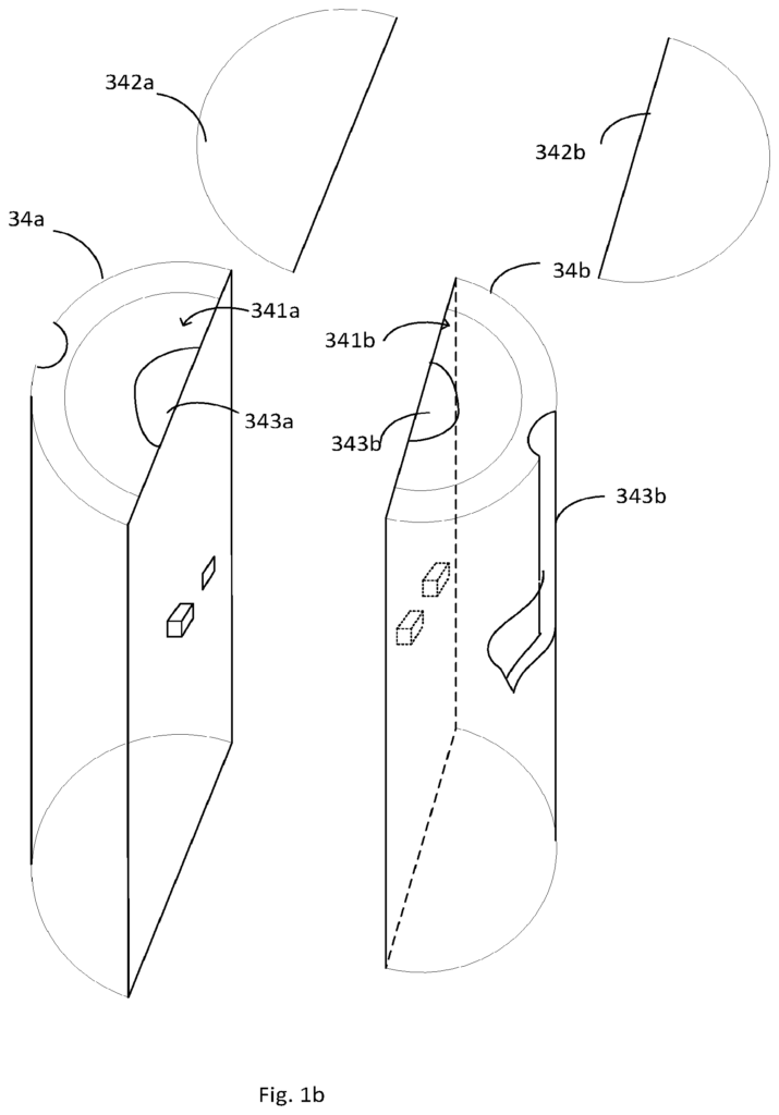
Now turn to FIG. The first alternative container member, 34 a, and the second alternative container member, 34 b, both have an exit 341a, 341b at one end. Sealing members 342a, 342b can be used to seal the outlets. These are usually metal foil, paper, or plastic films that can be adhered, bonded, or welded. These sealing members can be removed by tearing them off, before inserting the eliquid supply 34 in the container holder for the electronic cigarettes, or by using at least one spike or bayonet provided in the housing.
In one embodiment, each of the first and second container members 34 a has a portion cut off 343 a or 343b along the longitudinal axis. As shown in FIG., the cut-off can have a semi-cylinder form. The cut-off portion can be a semi-cylinder shape as shown in FIG. “When the two sections are brought together they form an aerosol passage, i.e. the central passage 32 for the aerosol produced at the heating unit on the electronic cigarette.
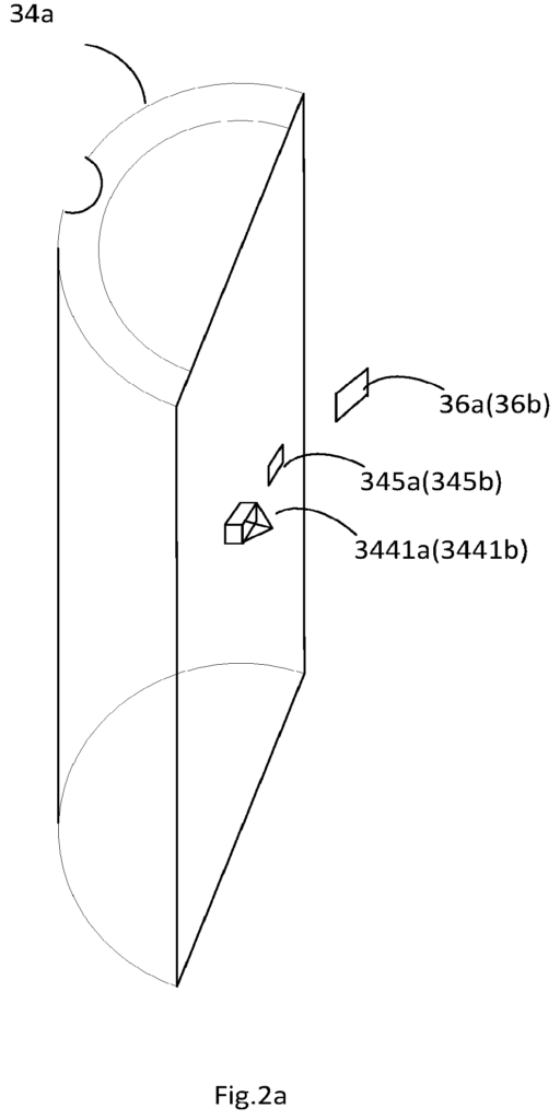
Normally, the container members are hollowed out and empty so they can be filled with bulk liquid e-liquid. The first container member (34 a) and second container member (34 b) may contain optional wadding 35 for holding the eliquid. Waddings can take any shape. As shown in FIG., the wadding can be a semiannular column. The wadding 35 can then be cut into the sections 343a and 343b shown in FIG. No longer is 1 b necessary. “The e-liquid can contain nicotine solutions of different concentrations, or different flavors.
![]()
Click here to view the patent on Google Patents.
Leave a Reply