Invented by Liang Cui, Siddharth EKBOTE, Weiqing Wu, Todd Sabin, VMware Inc
Virtual computing, also known as cloud computing, allows businesses to access computing resources and services over the internet, eliminating the need for on-premises infrastructure. This technology offers scalability, flexibility, and cost-effectiveness, making it an attractive option for organizations of all sizes.
However, one of the challenges with virtual computing is predicting the performance of virtual machines (VMs) and ensuring optimal resource allocation. VMs are the building blocks of virtual computing environments, and their performance directly impacts the overall efficiency and effectiveness of the system.
Traditionally, performance prediction in virtual computing relied on static models and rule-based algorithms. These methods often failed to accurately predict performance under dynamic workloads, leading to resource underutilization or overprovisioning. This resulted in increased costs and decreased performance.
Machine learning has emerged as a powerful tool to address these challenges. By leveraging historical data and real-time monitoring, machine learning algorithms can learn patterns and make accurate predictions about VM performance. These predictions enable businesses to optimize resource allocation, improve system efficiency, and reduce costs.
The market for machine learning prediction of virtual computing performance is driven by several factors. Firstly, the increasing adoption of virtual computing by businesses across industries has created a demand for accurate performance predictions. Organizations want to ensure that their virtual computing environments can handle their workloads efficiently and effectively.
Secondly, the complexity and variability of workloads in virtual computing environments make it difficult to develop static models or rule-based algorithms that can accurately predict performance. Machine learning algorithms, on the other hand, can adapt and learn from data, making them well-suited for predicting performance under dynamic conditions.
Furthermore, advancements in cloud computing technologies, such as the availability of large-scale datasets and powerful computing resources, have facilitated the development and deployment of machine learning models for performance prediction. This has opened up opportunities for startups and established companies to enter the market and offer innovative solutions.
Several companies have already made significant strides in this market. They offer machine learning-based platforms and tools that can analyze historical data, monitor real-time performance metrics, and provide accurate predictions. These solutions enable businesses to optimize resource allocation, improve system performance, and reduce costs.
Looking ahead, the market for machine learning prediction of virtual computing performance is expected to continue growing. As businesses increasingly rely on virtual computing environments, the need for accurate performance predictions will only become more critical. Machine learning algorithms will play a crucial role in meeting this demand and enabling businesses to maximize the benefits of virtual computing.

The VMware Inc invention works as follows
The disclosure provides a method for preventing failures of virtual computing instances transfers across data centres. In one embodiment, the flow control module collects the performance data primarily from components located at a local site as opposed to those in remote sites, when transferring a virtual machine from the local to remote site. Performance metrics are one type of performance information. The flow control module prepares features by normalizing data and if necessary, adding missing data. The flow control module inputs the feature data prepared into the machine learning models that have been trained to predict if a VM will transfer successfully or not, given the feature data input. If the prediction indicates that the VM will fail, remediation measures may be taken such as slowing the VM.
Background for Machine learning prediction of virtual computing performance:
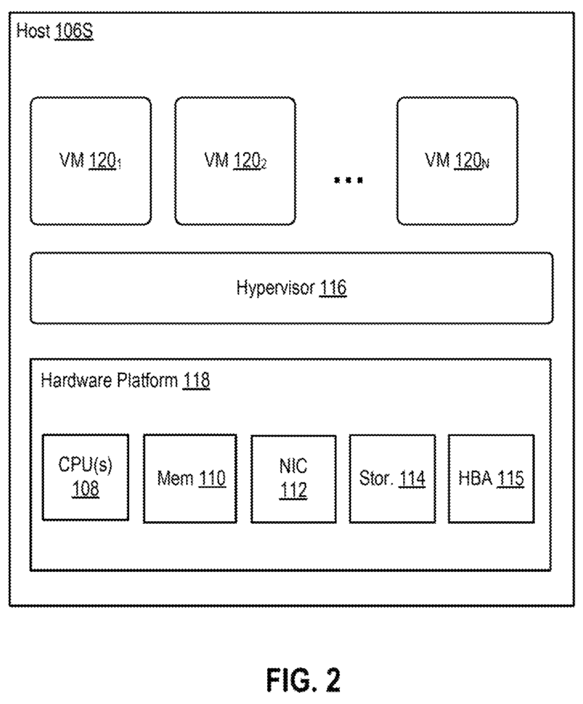
Computer Virtualization is a technology that involves encapsulating an entire computing platform into a virtual (VM) machine that is controlled by virtualization software that runs on a hardware platform (also called a ‘host computer’ herein). “or ‘host?’ Clusters are a grouping of computing platforms that provide resources to VMs. It is not uncommon to find hundreds or even thousands of VMs in a datacenter, running on several clusters.
Transfers between data centers of VMs can be done across various components such as hosts, service nodes (physical or virtual), network devices, network boosters (e.g. wide area network (WAN), optimizers), intermediate routing devices, etc. These components can be performing poorly and affect packet transmission, which in turn may cause the VM to transfer to fail. This wastes resources and leads to frustration for the user. It is not easy to gather information from remote components and from other components to control VM flow. In-flight information is also unpredictable because it depends on many variables, such as queue depths at intermediate routers and bandwidth delays. It is therefore difficult to predict bottleneck bandwidth as in-flight data sizes can vary.
One or more embodiments present a method for transferring a computing instance virtual from a data center in the first to another data center. The method includes, in general, receiving performance data associated with the transfer of the virtual computer instance from the data transfer path to the second datacenter. Using at least a model of machine learning and the performance information received, the method also includes predicting whether the transfer will be successful. The method further includes, in response to predicting the transfer of the computing instance won’t succeed, reducing the rate at which it is transferred.
Further embodiments” include a nontransitory computer-readable medium that stores instructions which, when executed by an computing system, cause the computing to perform the above method, as well as a computing programed to execute the above method.
Embodiments” presented herein present techniques to prevent the failure of virtual computing instances transfers across data centres. Virtual machines (VMs), which are used as an example of virtual computing instance, are not the only type of virtual computing instance that can be applied to. In one embodiment, a VM flow control module collects performance data primarily from components at a local site as opposed to those in a remote location, when transferring a VM between the local and remote sites. The collected performance data may include various metrics, such as disk I/O read rate, collected by a hypervisor in a host, data insertion rate, collected by a mobility agent, compression ratio, and throughput, collected by a wide-area network (WAN), and/or packet loss, network latency and throughput, collected by a gateway. Each of these may be considered features, as discussed further below. The flow control module performs feature prep by, for example, normalizing collected feature data or importing missing feature data if necessary. The flow control module then inputs the features prepared into one or more machine-learning models that were trained to predict if the transfer of a VM would succeed or fail based on input feature data. If it is predicted that the VM will not be transferred, remediation actions, such as slowing the VM down, may be taken.
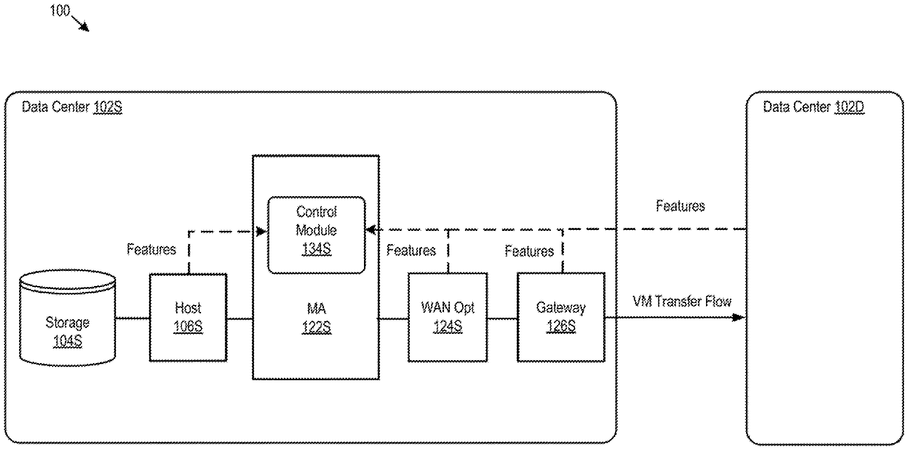
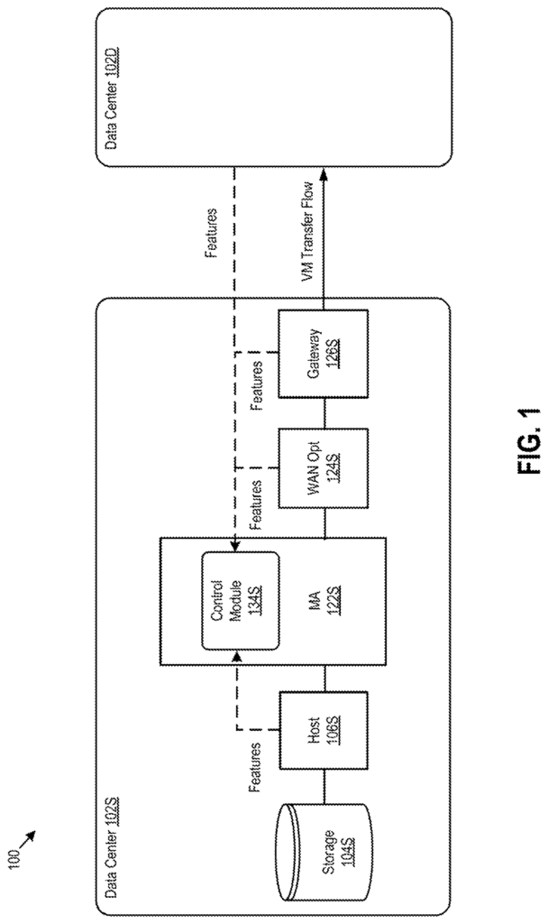
FIG. According to one embodiment, FIG. 1 shows an approach for smoothing the performance of virtual machine transfers using predictions from machine learning models. A cross-site computing 100 is shown to include a data center source 102S, and a data center destination 102D. A VM is transferred over a network from the source data center 102S, to the destination data center 102D. During the transfer of VM120, a VM flow control module 134 of a source mobility agents 122S collects information relating the transfer, creates a feature-vector from the information collected, and then inputs the feature-vector into machine learning models that each predict whether the transfer will be successful or not. Control module 134, although shown as a module in source mobility agents 122S may also be a separate module from source mobility agents 122S. For example, a separate module that runs in the same VM in communication with source mobile agents 122S. Failure of a VM Transfer can be defined as, e.g. the VM transfer timeout when a host destination does not receive transferred data after a predefined amount of time, such as 120 seconds. The machine learning models may be optimized using supervising techniques in order to optimize relationships among various factors. In one embodiment, each trained machine learning classifier may be a two-class classification that accepts feature vectors as inputs, and outputs labels indicating the success or failure for corresponding VM transfer, such as labels l1=0, and l2=1.
{\nVM\n?\n?\ntransfer\n?\n?\nsuccessful\n,\nif\n?\n?\nl\n=\n0\nVM\n?\n?\ntransfer\n?\n?\nfailure\n,\nif\n?\n?\nl\n=\n1\n\nWhen failure of the VM transfer is predicted, remediation action(s) may be taken, such as notifying a source VM transfer engine in a hypervisor running in source host computer 106S to slow down (also sometimes referred to as ?back off?) As discussed below, a data transmission rate for the VM transfer can be adjusted to prevent the transfer from failing. In another embodiment, machine learning models may be trained to predict success rates, or a predicted success rate. This is different from simply success or failure.
Control module 134, for example, collects performance data associated with the VM from a source host computer 106S that is transferring VM 120, a source mobility agent 122S and a source hypervisor. Each of these is discussed below in more detail. It should be noted that, although described separately, source mobility agent (122S), WAN optimizer (124S) and/or the source gateway (126S) may all run on the same physical or virtual machine or even in separate virtual or virtual machines. The collection of performance data primarily from local components (source data centers 102S, in this example) as opposed to remote components (destination data centers 102D, in this instance), eliminates the difficulties of collecting data from remote components. In certain embodiments, performance data may be collected from other sources than those shown on FIG. Middleboxes, other than WAN Optimizer 124, that transform, inspect or filter network traffic, are examples of such sources. Some performance data may also be collected by components of destination data centre 102D. For example, a hypervisor that runs on a host computer at the destination, or a gateway in destination datacenter 102D. In one embodiment, for example, the hypervisor in the destination host computing device may collect a data transfer rate and send it back to the control 134.
Host” 106S can communicate with external storage units 104S (shown in the figure as a unit of storage) via HBA 115 or NIC 112 Storage unit 104S can include any type of physical or logical store, including a logical store such as a logical number (LUN), or another logical store, exported from a physical system, storage area network (SAN), network-attached (NAS), disk arrays, other types of network data storage systems, or combinations of these. VM disk images stored in storage unit 106S (e.g. a disk of VM 120), are transferred to the destination storage unit during VM transfer. As part of performance information that is used to predict the success of a VM, control module 134 in one embodiment collects a hypervisor 116 read rate. “Disk input/output read rate” is the rate that data (of a VM image) are being read from a 104S storage unit during a VM Transfer.
Mobility agent 122S is an example of a source mobility agent. The destination data center 102D could also contain one or more destination agents (not shown). These mobility agents can run in VMs, or on hardware computers. In one embodiment, a source mobility agents 122S may include a simulator to allow the agent to simulate a source host for a VM to be transferred to the ultimate host in destination datacenter 102D. Similarly, a destination agent may also have a simulator to enable it to emulate a source host to transfer the VM to the ultimate host. During a VM, the mobility agent 122S of source datacenter 102S is a host that receives VM data from source host 106S. The data is then transmitted over a pair 126S and 126D gateways to a mobility agents in destination datacenter 102D. This mobility agent acts as a host which sends the data to a host at destination datacenter 102D. In the U.S. Patent Application Ser. No. No. 15/690 241, filed August 29, 2017, and entitled “Live Migration of Virtual Computing instances Between Data Centers”, This document is incorporated by reference herein in its entirety. Mobility agents 122S and 122D can also be used as data flow modules. Source mobility agents 122S may slow down data transfers by ‘throttling’. The rate at which the source mobility agent 122S receives or retrieves information from source host is?throttled’. See U.S. Patent Application Ser. No. No. This application is incorporated by reference in full. Control module 134, in one embodiment collects data insertion rate from mobility agent 122 to be used as part of performance information for predicting success of a VM Transfer. Data insertion rate is the rate at the VM data flows between source host 106S to source mobility agents 122S.
WAN Optimizer 124 is configured for increasing data transfer efficiency by, amongst other things, reducing the amount of data transmitted over a Wide Area Network (WAN). WAN Optimizer 124, for example, may be the WAN Optimizer described in U.S. Patent Application Ser. No. No. 14/838.537, filed August 28, 2015, and entitled “Data Center WAN Agregation for Hybrid Cloud Connection Optimization” or in U.S. patent application Ser. No. No. These are incorporated by reference herein in their entirety. Control module 134, in one embodiment collects throughput and compression ratio information from WAN optimizer 124 to be used as part of performance information for predicting the success of a VM. Compression ratio is the reduction of data representation expressed as a percentage (e.g. 10:1) and compression throughput is a rate at which data is compressed.
Source gateway 126S is connected to destination data center through a site interconnect comprising one or more connections, e.g. a WAN (e.g. Internet), Dedicated Direct Link, Multiprotocol Label Switching (MPLS), or?stretched? LAN. Source gateway 126S is connected to destination datacenter 102D by a site interconnect containing one or multiple connections. For example, the site interconnect may include a WAN, such as Internet, a dedicated direct connection, Multiprotocol Label Switching, or a “stretched” network. Layer-2 (L2) networks, local area networks (LANs), etc. Source gateway 126S can also manage IP addresses on the source host 106S for external internet protocol traffic and route traffic to and from source datacenter 102S. Source gateway 126S can also provide other networking services such as firewalls, network address translations (NAT), dynamic hosts configuration protocol (DHCP), load balancing and virtual private network (VPN), such as connectivity to a destination gateway in destination data center 102D. Control module 134, in one embodiment, collects packet loss, network throughput and network latency information from source gate 126S to be used as performance information for predicting the success of a VM. In this context, network latency is the time it takes to send a packet from a source to a target (e.g. a destination gateway) over a LAN. Network throughput is the amount of data that can be transmitted across a LAN in a certain time frame (e.g. in megabits or Gigabits per Second). Packet loss refers the percentage of packets that are lost.
FIG. The cross-site computing systems 100 are shown in more detail in FIG. The source data center, 102S, includes host computers 106S1 to 106D1 and storage units, 104D1 to 104D1n. Destination data centers 102D and 102D include hosts, storages, mobility agents, and gateways, 126D1 and 126D1 respectively. The host computer systems 106S1 and 106D1 at the source and destination data centers, as well as storage units 104S1 and 104D1 and mobility agents 122S1 and 122D1 and gateways 126S1 and 126D1 and 126S1 and 126D1 and 126D1 and 126D1 and 126D1 and 126D1 and 126D1 and 126S1 and 126D1 and 126D1 and 126D1 1. Mobility agents 122S1 to n in the source data center 102S can each have a VM flow control module as described above. And mobility agents 122D1 to n in the destination data center 102D can each have a VM flow control module.
Source virtualization manager 132S, which is shown in Figure 3, can communicate with one or more hosts 106S1-n via a network 128S. Source virtualization manager (132S) can communicate with hosts 106S1 to n over a network 128, and vice versa. Source virtualization manger 132S can run on a central server within source data center 102S or in a VM, e.g. in one of the hosts 106S1 to n. Source virtualization manger 132S can be configured to perform administrative tasks in source datacenter 102S. These include managing hosts 106S within source datacenter 102S, managing the VMs running on each host 106S. Source virtualization managers 132S can also be configured to integrate and manage virtualized computing services provided by destination data centers 102D into virtualized computing services of source data centers 102S in order to create a unified platform. Source virtualization manager may, for example, be configured to perform a VM transfer from source datacenter 102S into destination datacenter 102D or to deploy VMs to destination datacenter 102D and/or to perform other “cross-site” tasks. administrative tasks. “Although discussed in this document primarily with regard to virtualization manager 132S and/or 132D which integrate source and destination resources of data centers, it should also be understood that other types of software and even hardware can perform the functionality of virtualization managers described herein.
Some embodiments use machine-learning models to determine a data path to transfer a VM. This is in addition to using the model(s), to predict the success of a VM Transfer based on the performance information collected during VM Transfer, and to take remediation actions if it is predicted that the VM Transfer will fail. In cross-site computing 100, a data transfer path can include a series of components. As an example, FIG. The path shown in FIG.3 is?104S1,106S1,122S1,126S1,140, 126D1,122D2,106D1,104D1. There may be a set of paths between a storage-host source pair and destination storage-host. For example, the source storage-host pair and destination storage-host pair 104S1-106S1:104D1-106D1 defines a set of VM transfer paths including the ?104S1, 106S1, 122S1, 126S1, 140, 126D1, 122D1, 106D1, 104D1? Paths that start with the source storage and host pair 104S1 – 106S1 and finish with the destination storage and hosts 104D1 – 106D1 are also possible. The paths may be defined by, for example, two hosts, or two storages rather than source storage-host-destination storage-host pair. In one embodiment source control module 134S continuously gathers performance data, such as those described above, while VM transfers are being performed over a variety of paths. Source control module 134 then uses this information to predict the success rate or simply success or failure if a VM is to be transferred along these paths. Source control module 134S can collect performance data during real VM transfers or transfers of dummy VMs. Performance information may be collected and used to make predictions using dummy VMs of a small size (e.g. 1 GB per VM) that are periodically transferred. The source control module 134 uses machine learning models to predict the success rate if a VM was transferred over different paths based on collected performance data. Source control module then selects a route that is associated with a high success rate as discussed below.
FIG. According to one embodiment, FIG. 4 shows an approach to training and using machine learning models to predict the success of a virtual transfer. In the example shown, the training phase involves processing the received training data 402 at feature preparation 404, then training one or more machines learning models at 406 using a subset from the training data, and finally evaluating the machine learning model(s), using another subset, during the training. The training data can include performance information for representative VM transfer and labels indicating whether or not each representative VM transfer was successful. In one embodiment, training data may include disk input/output read rate, data insertion rates, compression ratios and throughputs, network latency, throughput and packet loss data from a plurality of representative VM transfer under different conditions. The data can also include a label indicating whether each representative VM transfer was successful or not. The representative VM transfers can be from different testbeds. For example, they may come from a testbed with a high throughput and low latency network, or a testbed with a low latency network but high throughput network, or testbeds that use different types of storage. The training data can provide empirical information about different combinations of computing environment, network conditions and storage devices. They may also include information on VM size, type, and parallelism. “Information collected during representative VM transfer with labels indicating whether the transfers were successful.
Feature preparation” at 404 comprises preparing initial training data for the machine learning. In one embodiment, the VM performance metrics described previously, namely disk I/O read rate, data insertion rates, compression ratios, compression throughputs, network latency and network throughputs, packet losses, etc., are all included. This feature is then considered. {The problem then becomes: given a pattern p represented by a set of d features, each of which is a performance metric collected at a point in time during a VM transfer, i.e., p?x=The problem is: Given a pattern p, represented by a collection of d features. Each feature represents a performance metric that was collected at a certain point during a VM Transfer, i.e. p?x=x1, x2. . . , xd, should remediation action(s) be taken to prevent failure of the VM transfer?|, xd? Should remediation actions be taken to avoid failure of the VM Transfer?} To solve this problem, features from representative VM transfer may be prepared and then used to train machine learning models that can predict success or failure. The predictions made by these machine learning models can then be used to determine the action to take. For example, slowing down the rate of data transfer of a VM to prevent a predicted transfer failure.
In one embodiment feature preparation can include normalizing data for the feature to fit within machine learning models and imputing any missing data using an imputation method. You can use any imputation method, even those that are known to people skilled in the field. After feature preparation, at 406, one or more machine-learning models are trained using a subset from the training data. In one embodiment, the majority of training data after feature preparation may be used for training the machine learning models and the minority used for evaluating the trained model. {During training and thereafter, the machine learning model(s) may each take as input a feature vector x=The machine learning models may take as input during training and afterwards a feature vector, x=x1,x2, . . , xd that includes prepared features (e.g., with normalized feature data and imputed data for features that are missing data) from a point in time during a VM transfer, and output a label indicating predicted success or failure of a corresponding VM transfer.|, xd, which includes features prepared (e.g. with normalized data for feature data, and imputed data to fill in missing data), from a particular point during a VM Transfer, and output a predicted label indicating success or failure of a corresponding VM Transfer.} In some embodiments one or more probabilistic and/or regression models can be trained at 406 in certain embodiments. The regression models can include, for example, support vector machines (SVMs), network(s) of logistic classification, and/or neural networks. Probabilistic models can include, for example, naive Bayesian networks. To train these models, any suitable algorithm or algorithms can be used. The particular algorithm(s), depending on the type of model being trained.
Evaluation” of machine learning models can include validating the model’s performance (e.g. a success rate that is above a threshold) and determining what model performs better in different situations. The trained model(s), as described, may be used to predict whether VM transfers will fail or succeed based on the collected performance data. Remediation actions can then be taken if the VM transfer is predicted to fail. In one embodiment, the trained models are evaluated by using them in a series of test VM transfer to predict whether the transfers will be successful or not, and then taking remediation actions when the predictions of failures occur. In this case, success rate can be defined as: Success Rate=Number Of Successful Transfers/Total No. of Transfers. In some embodiments, success rates may be based on observations made in the destination data centers, such as variations in data delivery rates, window sizes advertised, etc. These evaluations can determine how well trained models perform, and which trained model(s), under what circumstances, performs better. As discussed below, the evaluation results can be saved and used to choose one or more trained models to use for making predictions in a future VM transfer. The evaluation of trained models may include, in addition to evaluating the model(s), the accuracy of labels produced by the model(s), as compared to manually-specified label(s) on a small minority of training data that is used for validation.
Click here to view the patent on Google Patents.
Leave a Reply