Invented by Markus Dominik Mueck, Dario Sabella, Intel Corp
Wireless communication bands are divided into different frequency ranges, each of which is allocated for specific purposes such as mobile communication, broadcasting, or satellite communication. Within each frequency range, there are multiple channels available for use. These channels are like virtual lanes that allow different devices to transmit and receive signals without interfering with each other.
The management of preferred channel allocations involves determining which channels are best suited for specific applications or services. This decision is based on various factors such as the type of communication, the required bandwidth, and the level of interference from other devices or networks. Efficient channel allocation ensures that each device or service operates on a channel that provides the best performance and minimizes the risk of interference.
One of the key players in the market for management of preferred channel allocations is the regulatory bodies responsible for allocating and managing the wireless spectrum. These bodies, such as the Federal Communications Commission (FCC) in the United States, allocate specific frequency ranges for different purposes and regulate the use of these frequencies to ensure fair and efficient utilization.
Another important player in this market is the wireless service providers and network operators. These companies are responsible for managing their own network infrastructure and ensuring that their services operate on the most suitable channels. They need to constantly monitor the performance of their networks and make adjustments to channel allocations as needed to optimize performance and minimize interference.
In recent years, there has been a growing demand for more efficient management of channel allocations due to the increasing number of wireless devices and the growing complexity of wireless networks. The proliferation of smartphones, tablets, and other wireless devices has led to a significant increase in the demand for wireless communication services. This, in turn, has put pressure on network operators to optimize their networks and ensure reliable and high-quality services.
Furthermore, the emergence of new technologies such as 5G and the Internet of Things (IoT) has further increased the complexity of wireless networks and the need for efficient channel allocation. These technologies require higher bandwidth and lower latency, which can only be achieved through careful management of channel allocations.
As a result, there is a growing market for solutions that can help network operators and service providers manage their preferred channel allocations more efficiently. These solutions often involve advanced algorithms and software tools that can analyze network performance, predict interference, and optimize channel allocations in real-time. Companies specializing in network optimization and wireless communication management have emerged to cater to this growing demand.
In conclusion, the market for management of preferred channel allocations among wireless communication bands is a rapidly growing and important sector. With the increasing demand for wireless communication services and the complexity of modern wireless networks, efficient channel allocation has become crucial for ensuring optimal performance and minimizing interference. Regulatory bodies, wireless service providers, and specialized companies are all playing a significant role in this market by developing solutions and technologies to meet the growing demand for efficient channel allocation management.

The Intel Corp invention works as follows
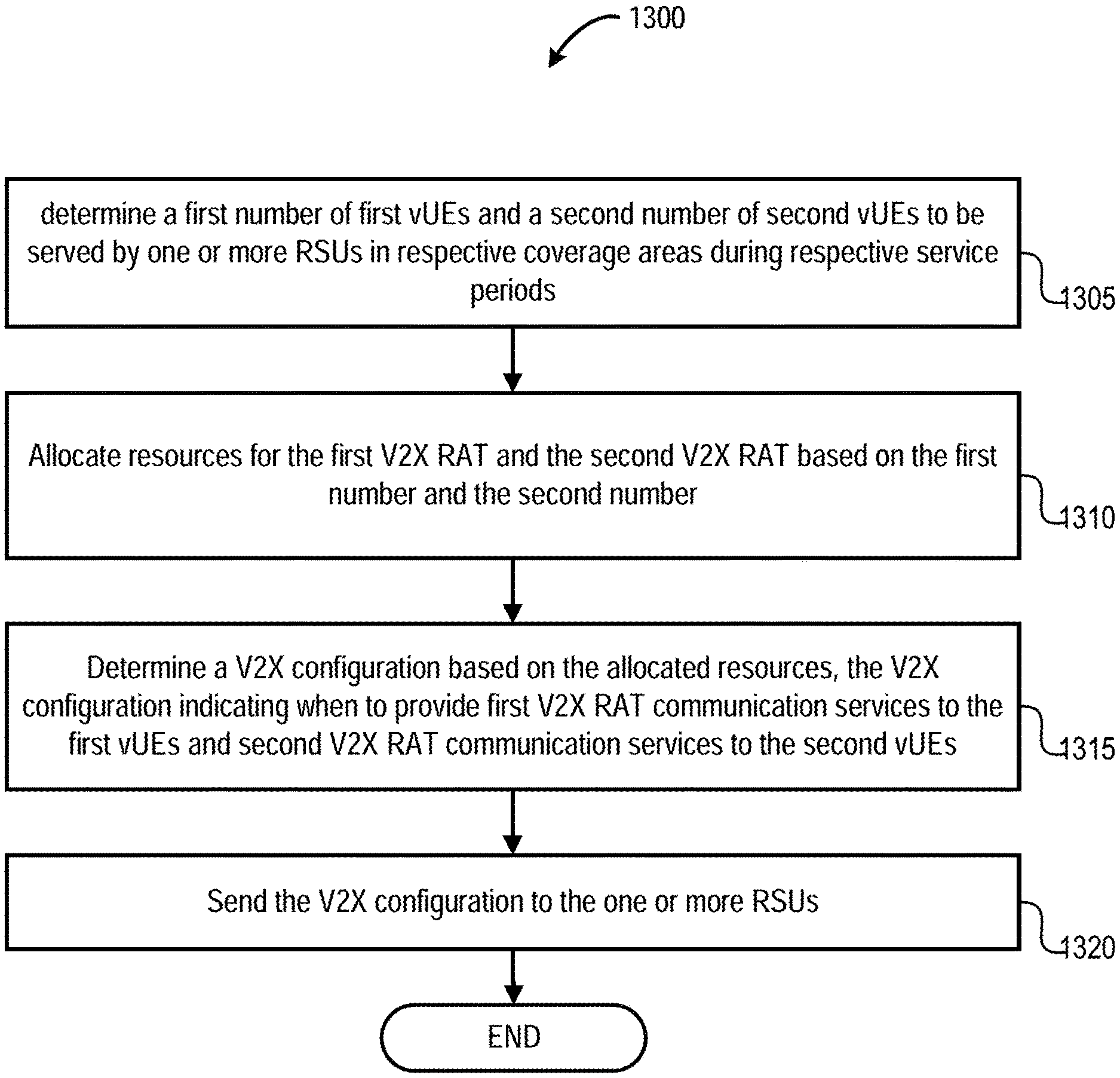
Various systems and methods for establishing, configuring, and operating multi-access edge computing (MEC) communications, such as in connection with management of preferred channel allocations between two or more vehicle-to-everything (V2X) Radio Access Technologies (RATs), are discussed herein. In some embodiments, resource allocations (such as channel allocations) are determined for vehicle user gear (vUEs), based on the number of vUEs that support each of one of more V2X radio access technologies (RATs) detected in one of more coverage areas by one or multiple Road Side Units. Other embodiments may be described or claimed.
Background for Management of preferred channel allocations among wireless communication bands
Internet of Things devices can be physical or virtual objects, which may communicate over a network. They may also include sensors, actuators and other input/output elements, for example, to collect data from the real world or to perform actions. IoT devices can include low-powered sensors that are attached or embedded into everyday objects, such as vehicles, buildings, packages, etc. to give them an artificial sense of perception. IoT devices are becoming more popular, and applications that use these devices have multiplied. IoT devices, Multi-access Edge Computing services (MEC), and other advanced scenarios at the edge of the networks have been introduced by the deployment of IoT and MEC. These advanced use cases also brought with them a variety of technical challenges relating to security, computing/processing resources, networking resources, service availability, and efficiency.
MEC provides application developers and content provider with cloud computing capabilities, as well as an Information Technology (IT), service environment at edge of network. This environment is characterized with ultra-low latencies and high bandwidth, as well as real time access to radio network data that can be leveraged by the edge applications (e.g. MEC applications). MEC technology allows for flexible and rapid deployments of innovative services and applications towards mobile subscribers, enterprise and vertical segments.
In the following description, method, configurations and related apparatuses for managing coexistence and interoperability among multiple vehicular communications systems (or standards) are disclosed, including preferred channel allocations in relation to multiple radio communication technologies, as well as Multi-access Edge Computing services and communication architecturals.
Currently, there are two competing vehicular communication systems (or vehicle-to-everything (V2X) radio access technologies (RATs)); one system is Institute of Electrical and Electronics Engineers (IEEE) 802.11p such as Dedicated Short Range Communication (DSRC) and Intelligent Transport Systems in the 5 gigahertz (GHz) frequency band (ITS-G5), and the other system is Long Term Evolution (LTE) cellular V2X communication (C-V2X). The term ‘DSRC’ is used in this document. The term?DSRC? refers to vehicular communication in the 5.9 GHz band. “These systems are not designed to coexist and they are not usually interoperable.
?Interoperability? Refers to the ability for vehicle UEs, roadside equipment and Road Side Units to communicate using one vehicular communications system with other vUEs or roadside equipment that uses the other vehicular communications system. ?Coexistence? Coexistence refers to the sharing or allocation of radiofrequency resources between vUEs, roadside equipment and vehicular communication systems. The ‘preferred channel’ is one coexistence method. This approach involves dynamically allocating the channels that will be exclusively used by one system, or exclusively by the opposite system. The ‘co-channel existence’ is another coexistence strategy. This approach involves assigning both systems to the same channel at different times.
As a context for the applicable standardization and regulation, three safety channels each of 10 megahertz are assigned in the 5.9GHz ITS band. The 5G Automotive Association (5GAA), has proposed a “safe-harbor” approach, where one channel would be allocated to DSRC/ITS G5 and another channel to LTE C V2X on a fixed basis (upper/lower channel). In the short term, it is recommended that the middle channel be left unused. This proposal was rejected by the Electronic Communication Committee of the Conference of Postal and Telecommunications Administrations of (CEPT),?SRDMG (17)136 ITS Background?Short Prel action plan and background as well as reporting to ECC #46? (?SRDMG? SRDMG has stated that the preferred channels approach may be viable. SRDMG stated instead that the preferred channel approach could be viable. This dynamic allocation could be negotiated between systems instead of a fixed channel allocation to DSRC/ITS G5 and LTE V2X. This approach is also considered inefficient.
The technical approach described here does not provide a fix allocation for multiple vehicular communication technologies that access the same band (e.g. DSRC/ITS G5 and LTE V2X). Edge network infrastructure (e.g. an RSU, or a colocated MEC host/server) determines the amount of spectrum required for each vehicular communications system based upon the number of vUEs that use each type of vehicular technology. It then dynamically (or partially-statically), assigns a channel allocation preference (depending on local requirements), and sends this allocation (or an indicator of the decision to allocate) to neighboring infrastructure. In an alternative embodiment the vUEs request a particular vehicular communication technology and the edge infrastructure dynamically (or partially-statically), assigns resources according to the number of requests.
The following discussion introduces a method to support the preferred channels and dynamic channel allocation among multiple vehicular RATs. The following discussion introduces an approach to use MEC and Edge Network entities in support of the preferred channels approach and the dynamic allocation of channels among multiple vehicular RATs (also referred to as “V2X RATs”). The technical approach described here is acceptable to regulatory administrations. (They allow for dynamic allocation called “preferred channels”). The technical approach discussed herein is acceptable by regulation administrations (they allow for a dynamic allocation, called?preferred channels? “Also, a solution which includes both technologies (e.g. the technology neutral approach) will improve interoperability and allow V2X/ITS to be offered across broader deployments.
The following description is a detailed explanation of these techniques in MEC systems and service deployments, which are applicable to broader contexts of Internet of Things (IoT), fog networks and fog device deployments. The disclosed MEC systems and services deployment examples are intended to be an illustrative illustration of a fog system or device, but many other combinations of devices at the edge can be used. The techniques disclosed herein can also be applied to other IoT configurations and standards, as well as other architectures and intermediate processing entities. The techniques and configurations described herein may be of significant benefit to MEC architectures, and other IoT devices network architectures that involve any number edge computing devices or fog computer platforms.
For illustrative purposes, the following description is provided for deployment scenarios including vehicles (including computer-assisted and/or autonomous vehicles) in a two dimensional (2D) freeway/highway/roadway environment wherein the vehicles are automobiles. The embodiments described in this document are applicable to other vehicle types, including trucks, buses, motorboats and motorcycles. They can also be applied to any motorized device capable of transporting goods or people, such as electric personal transporters. The embodiments of the present invention are also applicable to social networking among vehicles. The embodiments described in this document may also be applied to 3D deployment scenarios, where some or all vehicles are implemented as flying devices, such as drones, unmanned aircraft vehicles (UAVs), or any other motorized device.
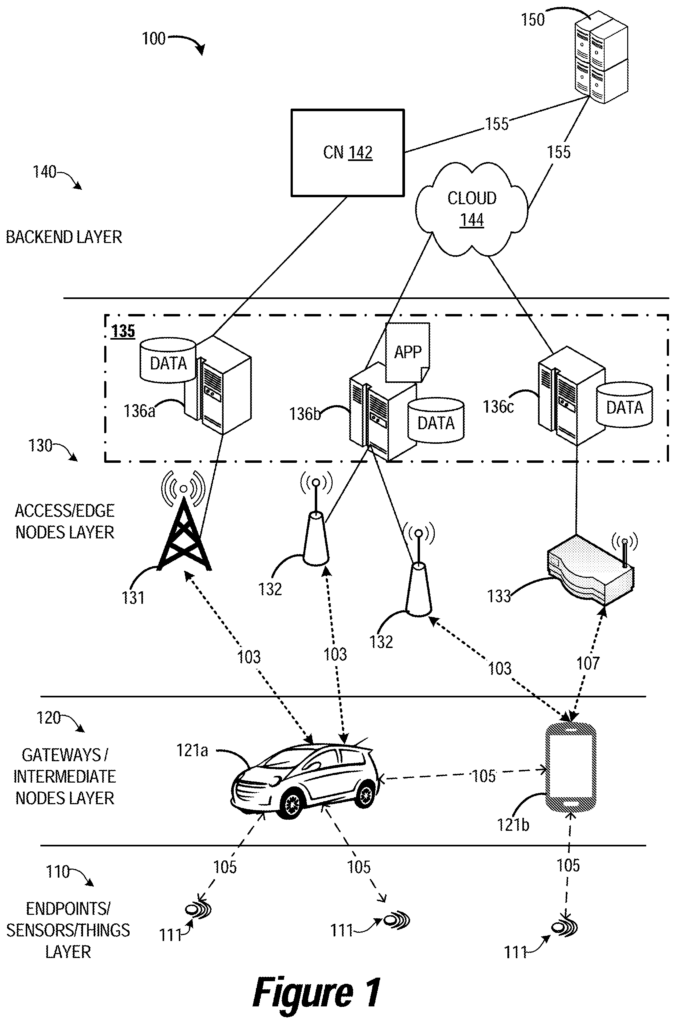
Referring to FIG. 1. This figure illustrates an environment for Multi-access Edge Computing 100 according to various embodiments. FIG. FIG. 1 illustrates in detail the various layers of communication that occur within the environment 100. Starting with endpoint sensors or things 110 (e.g. operating in an IoT topology), comprising at least one IoT device 111, gateways or intermediate layer 120, comprising user equipment (UEs), 121 a, 121b, which facilitates the collection and process of data from the endpoints; increasing in processing sophistication and connectivity to access or edge layer 130, comprising access nodes (ANs “The processing at the backend 110 may be enhanced through network services performed by a cloud service provider 150 or a remote application server.
For example, an end-user device such as an endpoint 110 or intermediate node 120 has access to different communication networks based upon different technologies. These include LTE, NR/5G cellular (e.g. as provided by AN 131 or ANs 132), DSL or MuLTEfire for application services. The choice of access networks (e.g. WiFi, LTE etc.) will determine the performance of applications in various scenarios. The network and transport protocol (e.g. VPN, MPTCP etc.) is also important. WiFi, for example, may offer high throughput to intermediate nodes and endpoints when the coverage is good, but this throughput will degrade as users move closer to the edges of WiFi coverage or when a 133 serves an extremely large population (e.g. due to contention-based WiFi access scheme). The limited spectrum available in LTE and NR networks can limit the network’s capacity. However, quality is still predictable, even when there are multiple users. This is due to the exclusiveness of the licensed spectrum as well as the scheduling controlled by a base station.
Unlike LTE or NR networks, which use licensed spectrum to operate, WiFi is a share medium that operates on the unlicensed radiofrequency ranges of 2.4 GHz and 5.8 GHz. LAA is the 3GPP version of unlicensed spectrum. LAA aims to create LTE or NR specifications that are globally harmonized and allow fair coexistence between WiFi and other networks on a shared medium. LAA uses a similar medium access scheme to WiFi’s EDCA. Both standards are also challenged by the coexistence effect on fairness and performance with regard to LTE or NR. When using network technologies operating on a shared medium, it is possible that packets are lost during transmission. This can be due to temporary interference, collisions of packets, congestion and buffer overflow. In WiFi-based protocols today, MAC protocols allow for limited retransmissions in order to recover lost packets. WiFi transmitters will drop packets when the maximum number of retransmissions is reached. WiFi-based retransmission is also not applicable when packets are dropped because of temporary congestion or buffer overflow. LAA also uses a contention-window size (CWS), where the CWS increases exponentially based on HARQ ACK at the MAC layer.
Referring to FIG. The environment 100 shown in FIG. or ?UEs 121?). The UE 121 a in this example is a vehicle UE and the UE 121 b a smartphone. These UEs 121 can be any mobile or nonmobile computing device such as tablets, wearables devices, PDAs or pagers. They could also include desktop or laptop computers, wireless handsets or unmanned vehicles. These UEs 121 may include any mobile or non-mobile computing device, such as tablet computers, wearable devices, PDAs, pagers, desktop computers, laptop computers, wireless handsets, unmanned vehicles or drones, IVIs, ICEs, an Instrument Clusters, HUDs, OBDs, DMEs, MDTs, OBUs, EMS, EEMS, ECUs, ECMs, embedded systems, microcontrollers, control modules, networked or?smart?
Environment 100 includes IoT devices 111. These are embedded computing devices that are uniquely identifiable (e.g. within the Internet infrastructure). They comprise a network-access layer designed for IoT applications with low power consumption and short-lived UE connection. IoT devices can be objects, devices or sensors. The IoT devices 111 can be any objects, sensors, devices or “things” embedded with software and/or hardware components. Capable of recording and/or capturing data related to an event and communicating this data over a network without user intervention. In various embodiments, IoT device 111 can be abiotic devices like autonomous sensors, gauges or meters, image capture devices and microphones, audio emitting devices and audio playback devices. The IoT devices 111 can use technologies such as M2M or MTC for exchanging data with an MTC server (e.g., a server 150), a metering system, a sensor network and/or IoT networks. IoT devices can use technologies like M2M and MTC to exchange data with an MTC (e.g. server 150), MEC server 136, MEC system or device, via PLMN, D2D or ProSe communication, sensor networks or IoT network. M2M and MTC data exchanges can be initiated by machines.
The IoT devices can execute background applications, such as status updates and keep-alive messages. To facilitate the connection of the IoT Network. The IoT network can be a Wireless Sensor Network (WSN) when the IoT device 111 is embedded or attached to a sensor device. IoT networks are interconnected IoT UEs. For example, the IoT devices can be connected via direct links 105. IoT devices can include a variety of different devices grouped together in various combinations. This may include IoT device that provides one or more services to a specific user, customer, organization, etc. The service provider (e.g. an owner/operator server 150, cloud 144, and/or CN 412) may deploy IoT devices to a specific area (e.g. a geolocation or building). In order to provide one or more of the services. In some implementations the IoT network can be a mesh of IoT devices, which is sometimes called a fog system or fog. It operates at the edge cloud 144. Fog computing is a system-level horizontal architecture that distributes resources and services of computing, storage, control, and networking anywhere along the continuum from cloud 144 to Things (e.g. IoT devices 111). Fog computing is an architecture horizontal system that distributes computing, storage and control resources, as well as networking and networking services, anywhere along the continuum, from cloud 144 up to Things (e.g. IoT devices 111). The fog can be created according to specifications published by the OFC and the OCF. In some embodiments the fog can be a tangle, as defined by IOTA.
The fog may be used to perform low-latency computation/aggregation on the data while routing it to an edge cloud computing service (e.g., edge nodes 130) and/or a central cloud computing service (e.g., cloud 144) for performing heavy computations or computationally burdensome tasks. Edge cloud computing, on the other hand consolidates human-operated resources into a cloud. These voluntary resources may include, for example, intermediate nodes and/or endpoints 120, desktop PCs and tablets, smartphones and nano data centers. The edge cloud resources may be located within a one-to-two hop distance of the IoT devices 110, reducing the overhead associated with processing data as well as network delays.
In some embodiments, fog could be a consolidation IoT devices and/or network devices such as switches and routers with high computing power and the capability to run cloud applications logic on the native architecture. Cloud vendors may manufacture, manage, and deploy fog resources. They may also be connected by high-speed, reliable links. Fog resources are located farther away from the edge than edge systems, but they’re closer to a cloud infrastructure. Fog devices can be used to handle workloads or tasks that are computationally intensive and have been offloaded from edge resources.
In some embodiments, fog can operate on the edge of cloud 144. The fog at the edge 144 of the cloud may overlap with or be subsumed in an edge network 130. Edge network 130 of cloud 144 can overlap or be subsumed into the fog. The fog can also be an edge-fog system that consists of an edge layer and fog layer. The edge layer is a loosely coupled collection of resources that are operated by humans (e.g. the compute nodes and edge devices mentioned above). The Fog layer is located on top of the Edge layer. It is a consolidation or networking devices, such as intermediate nodes and/or endpoints of FIG. 1.
Data can be recorded, stored/recorded and transmitted among IoT devices 4804, or, for example, between the intermediate nodes and/or endpoints that have direct connections 105 (as shown in FIG. 1). Aggregators that communicate with IoT devices and each other via a mesh networking can implement the analysis of traffic flow and control schemes. The aggregators can be IoT devices 111 or network appliances. In the FIG. In the example of FIG. The aggregator can upload data to the cloud, and receive commands from the cloud through gateway devices in communication with IoT devices and aggregators via the mesh network. In some implementations, unlike the traditional cloud computing models, the cloud 144 might have very little computational capability and serve only as a repository to archive data processed and recorded by the fog. In these implementations the cloud 144 is a centralized storage system that provides reliable access to data for computing resources on the edge and/or fog devices. The Data Store of the Cloud 144, which is at the core of the Architecture, can be accessed by the Edge and Fog layers of the edge-fog networks.
![]()
The UEs 121, IoT devices 111, or a combination of them, may be configured in a way to communicate with the Radio Access Networks (RANs) that include one or more ANs 131, 132, and/or 133. In some embodiments, a RAN can be an NG RAN (or a 5G RAN), an E-UTRAN (or a legacy RAN), such as a UTRAN. The term ‘NG RAN’ is used in this document. As used herein, the term ‘NG RAN’ The term RAN or something similar may refer to a system that uses LTE or 4G. The UEs 121, and IoT devices 111, may use respective connections (or channel) 103. Each of these channels comprises a physical communication interface or layer. In this example the connections 103 have been illustrated as air interfaces to enable communication coupling. They can be compatible with cellular communications protocol such as a GSM, a CDMA protocol or network, a PTT, a POC, a 3GPP LTE, a 5G, a NR, a 3GPP LTE, a 3GPP LTE, a 3GPP LTE, a UMTS, a 3GPP LTE, a 3GPP, a
Click here to view the patent on Google Patents.
Leave a Reply