Invented by Hung Nguyen, Gigamon Inc
Virtualization allows businesses to consolidate their hardware resources, improve scalability, and reduce costs. However, it also introduces new complexities in managing and monitoring network traffic. Traditional network monitoring tools are often ill-equipped to handle the dynamic nature of virtualized environments, leading to blind spots and potential security vulnerabilities.
Monitoring virtualized networks requires specialized tools that can provide visibility into virtual machines (VMs), virtual switches, and virtual network functions (VNFs). These tools should be able to capture and analyze network traffic within the virtual environment, identify performance bottlenecks, and detect any anomalies or security threats.
One of the key drivers for the market growth is the increasing demand for real-time monitoring and analytics capabilities. With virtualized networks, IT teams need to be able to quickly identify and resolve performance issues to minimize downtime and ensure a seamless user experience. Real-time monitoring tools provide instant visibility into network traffic, allowing IT teams to proactively address any issues before they impact the business.
Another factor contributing to the market growth is the rise of software-defined networking (SDN) and network functions virtualization (NFV). SDN and NFV technologies enable organizations to abstract network functions from the underlying hardware, making it easier to deploy and manage virtualized networks. However, this also introduces new challenges in monitoring and ensuring the performance of these virtualized network functions. As a result, there is a growing demand for monitoring solutions that can effectively monitor and manage SDN and NFV deployments.
Furthermore, the increasing adoption of cloud computing and hybrid cloud environments has further fueled the demand for monitoring virtualized networks. As organizations move their workloads to the cloud, they need to ensure that their virtualized networks are performing optimally and securely. Monitoring solutions that can provide visibility into both on-premises and cloud-based virtualized networks are becoming increasingly important.
The market for monitoring virtualized networks is highly competitive, with several established players and emerging vendors offering a wide range of solutions. These solutions vary in terms of features, scalability, and integration capabilities. Organizations should carefully evaluate their monitoring requirements and choose a solution that best fits their needs.
In conclusion, the market for monitoring virtualized networks is experiencing significant growth as organizations increasingly adopt virtualization technologies. The demand for real-time monitoring, the rise of SDN and NFV, and the adoption of cloud computing are driving the need for specialized monitoring solutions. As virtualized networks become more prevalent, organizations must invest in effective monitoring tools to ensure optimal performance, security, and scalability.

The Gigamon Inc invention works as follows
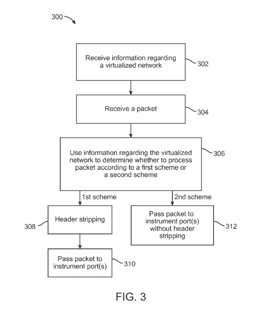
The method for monitoring virtualized networks includes receiving information about the virtualized system, which is received via a port on a switch appliance. It also involves receiving a packet through a network port, using the received data to determine whether the packet should be processed according to a 1st packet processing or 2nd packet processing, the first scheme involving header stripping and packet transmission from the switch appliance to one instrument port, with each instrument port configured to communicate with a monitoring device.
Background for Monitoring virtualized network
Network switches were used to send packets from one network node to another. These network switch devices have a network port that receives packets from one node and another network port that passes the packets on to a different node. Some network switches may include instrument ports that allow packets to be sent to instruments used for network traffic monitoring.
The applicant of the subject application determined that it could be desirable to have network switch devices that can process virtualized packets associated with virtualized networks, as well as normal packets associated with non-virtualized networks.
The method includes receiving information about the virtualized networks, which is received via a port on a switch appliance. It also includes receiving a packet through a network port, using the information received to determine whether the packet should be processed according to a 1st packet processing or 2nd packet processing, wherein a 1st packet processing involves header stripping and then performing packet transmittal to one instrument port at the switch appliance. Each of the instrument port are configured to communicatively couple to a monitoring network instrument.
The following embodiments are also possible: “An apparatus that is communicatively connected to a virtualized virtual network has a port to receive information about the virtualized virtual network, a networking port to receive a packet, multiple instrument ports with each instrument port configured to communicately couple to a monitoring instrument for the network, and a processor unit to use the information received to determine whether the packet should be processed according to a 1st packet processing method or 2nd packet processing method, wherein 1st packet processing
The apparatus can be configured in a number of ways. It may include a plurality instrument ports that are configured to communicate with a network monitoring device.
The following detailed description will reveal additional aspects and features.
The figures are used to describe various embodiments. Note that the figures have not been drawn to scale, and that similar elements or functions in the figures are all represented with the same reference numbers. The figures are intended only to aid in the description of embodiments. The figures are not meant to be an exhaustive description or a limit on the scope of invention. A illustrated embodiment does not need to include all aspects or benefits. “An aspect or advantage described with respect to a specific embodiment does not have to be limited to this embodiment. It can also be used in other embodiments, even if they are not illustrated or described explicitly.
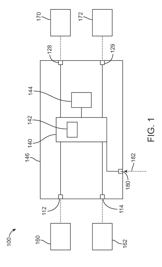
FIG. According to some embodiments, FIG. 1 shows a network switching device 100. The network switch 100 has a first port 112, a secondary port 114 and two instrument ports 129. The device 100 includes a packet (switch) module 140, which has a processing unit, a processor, and a housing for the packet switch 140. In the embodiments illustrated, the device 100 includes additional components such as a Network PHY (not shown), coupled to each port 112, 114. The Network PHYs can be considered parts of packet switch 140. The Network PHYs can also be considered as components separate from the integrated chip 140. The PHY connects a link-layer device to a physical media such as an optical fibre, copper cable, or the like. In some embodiments, in place of the PHY the device 100 can include an optical transceiver or a SERDES. The housing 146 enables the device 100 be transported, sold and/or operated in a single piece. Ports 112, 114 and 128, 129 can be found at the periphery 146 of the housing. Ports 112, 114 and 128, 129 can be located in other places relative to the housing. In other embodiments the device 100 could include more than just two network port 112,114. “Also, even though two instrument ports are shown in the figure, other embodiments of the device 100 could include just one instrument port or more than two.
During use, the device’s first network port 112 is communicatively connected (e.g. via a computer network such as the Internet), and the second network port 114 is also communicatively connected (e.g. via a computer network such as the Internet), to a node no. 162. The device 100 can communicate packets via network ports 112,114 between the nodes 160 and 162. The instrument ports 128,129 of the device are also communicatively connected to the respective instruments 170 and 172 during use. Instruments 170,172 can be directly connected to the device or communicated with the device through a network (e.g. Internet). In some cases the device 100 can be provided as a unit, allowing it to be deployed in a single location along a communications path. In the embodiments illustrated, the packet switches 140 are configured to receive packets via network ports 112,114 from nodes 162, and then process them according to a predefined protocol. The packet switch 140, for example, may send packets from one or multiple nodes to instrument ports 128, 129. In some embodiments one or more network ports 112,114 may be configured for normal packets to be received (e.g. packets that are not from a network virtualized) as well as virtualized packages (e.g. packets in tunnel format which include encapsulation resulting from virtualization technology). In some embodiments, the network ports 112,114 are configured to only receive virtualized packets.
In one or more embodiments the packet switch may be any switch that transmits packets in accordance to a predetermined transmission scheme. In some embodiments the packet switch 140 can be configured by a user so that packets are transmitted one-to one (i.e. from a network port to an Instrument port). The term “instrument port” is used throughout this specification. Any port configured to transmit packets is referred to as an?instrument port’. The instrument can be either a non-pass-through device, such as a sniffer or a device that can receive and process packets but not transmit them back, such as an intrusion protection system. In other embodiments the packet switch may be configured so that packets can be transmitted from a single network port to multiple instruments ports. In other embodiments the packet switch may be configured so that packets can be transmitted using a multiple-to-many (i.e. from multiple network port to multiple instrument port) configuration. In other embodiments, packet switch 140 can be configured to transmit packets in a multiple-to-one (i.e. from multiple network port to one instrument) configuration. In some embodiments the user can select from the many-to many, many-to one, or one-to one configurations to configure the device so that packets (or specific types of packets), are routed according any of these configurations. In some embodiments, a predetermined configuration for packet movement is used. This means that the device 100 can automatically route packets to ports according to the predetermined configuration.
Examples” of packet switch140 that can be used to implement the features described in this document include commercially available switch devices such as GigaVUE, which is available from Gigamon LLC. U.S. Patent Application Ser. Nos. Nos.
According to some embodiments, a packet switch 140 can have all the functionality of a conventional switch but it also provides visibility in various areas of a network. So, some embodiments of packet switch 140 can operate as a managed packet switch but with packet monitoring. The packet switch 140 is configured to act as a circuit-switch under certain conditions. In some embodiments the configuration of the managed switch can be done by using a switch’s CPU interface to modify registers to perform the desired operation. In some embodiments, packet switch 140 can be “out-of band”. The network switch is configured to receive packets and send them to an instrument, or a network other than the one associated with the packets’ original destination.
It should be noted that packet switches 140 of different configurations can be used in addition to those described above. In one or more embodiments, the packet switches 140 can be implemented by an integrated circuit such as a CPU (e.g. a general-purpose processor, network processor, ASIC processors, FPGA processors, etc.). The term “packet switch” is used to describe this. The term ‘packet switch? “Any circuit capable of performing functions described in this document is acceptable and does not have to be a switch or processor.
As shown in the figure the network switch device includes an additional port 180 that receives information 182 about a virtualized networking. The information 182 about the virtualized network can be, for example, an identification or a virtual host, a virtual workload, a mapping of the virtual host to the virtual workload, or a combination thereof. In some embodiments the information 182 can be a mapping of an outer header (e.g. the addresses for the source and/or the destination VM hosts), and an inner header (e.g. the addresses of a virtual machine) in a packet with a tunnel format. The outer header could be due to a virtualization-related encapsulation. Information 182 about the virtualized network can be received by the port 180 from the virtualized data center or virtual machine host. It may also come from an openflow controller, network switch or other device communicatively connected to the port. In some embodiments the port 180 can be a different port than the network ports 112. In some embodiments, the ports 110, 114 are network ports, and the port 180 can be implemented by using either or both network ports. In these cases, the port 180 can also receive network traffic being transmitted between nodes, such as nodes 160 and 162. In other embodiments, device 100 can include multiple ports 180 to receive information 182. One or more ports 180 can be used as network ports 112,114 in some cases.
According to some embodiments the processing unit is configured to receive the packets from the ports 112,114 and to process them in relation to the information 182 received by the port 180 regarding a virtualized networking. In some embodiments the processing unit may determine, based on information 182, that a packet is associated to a virtualized system. The packet switch 140 will then process the packet according to a first packet-processing scheme. In some embodiments, the processor 142 can determine that a packet is not connected to a virtualized system based on information 182, and then the packet switch 140 will process the packet according to a second scheme. In certain embodiments, a first packet processing scheme can involve header stripping of the packet associated with a virtualized networking using the processor. The packet is then transmitted to the instrument ports 128 or 129 on the network switch device. Below, we will discuss header stripping techniques in more detail. In some embodiments, a second packet processing scheme could involve sending packets to the instrument ports 128 and/or 129 of the network switch device without header stripping.
In the illustrated examples, the processing module 142 is shown as a component within the packet switch 140. In some embodiments, the processor 142 can be a separate part from the packet switching 140. The processing unit may be implemented by a processor such as a general or network processor, ASIC, FPGA, etc. In some embodiments, the processor 142 can be a field-processor. In other embodiments, processing unit 142 can be a network-card. In some embodiments, the ternary-content-addressable (TCAM) memory may be included in the packet switch. The packet switch 140 can be configured to perform a variety of packet processing functions. This includes but is not limited to, packet filtering and routing, packet switching, mirroring packets, packet aggregation etc.
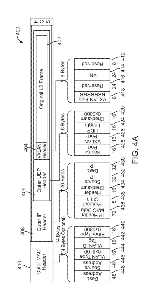
As discussed, in certain embodiments the processor 144 can be used to strip headers. The processor 144 communicates with the packet switch 140. In some embodiments, processor 144 can be part of packet switch 140. In some embodiments, processor 144 can be a general-purpose processor, network processor or ASIC processor. In other embodiments the processor 144 can be any type of hardware, software or combination that is configured to perform header removal (and optionally other packet processing functions). In the embodiments illustrated, the processor is configured to only receive packets that have a tunnel format. This includes packets used in virtualized networks. In one implementation the processing unit 140 or packet switch 142 is configured to only pass packets having a tunnel-format to the processor. It does not pass any packets without a tunnel-format (e.g. packets not associated with virtualized networks) to the processer 144. The processor 144 removes headers when it receives a packet in a tunnel format. The processor 144 can be configured, as non-limiting examples show, to remove from the packet an outer MAC, outer IP, outer UDP, or any combination thereof. Below, examples of these headers are discussed with reference to FIGS. 4A-4B. “In other embodiments, the processor 144 can be configured to perform packet processing functions other than packet stripping.
The packet switch 140 then transmits the packet to one or more of the instrument ports 128, 129 according to a predetermined transmission scheme (e.g., one-to-one, many-to-1, many/one, etc.). The packet switch transmits the packet according to a predetermined transmission scheme to one or several of the instrument ports 128 and 129. As discussed previously.
As previously discussed, the processor 142 can determine that a particular packet is not part of a virtualized system. In this case, the processing module 142 or packet switch 140 will process the packet according to the second packet-processing scheme, where the packet is sent directly to one or several instrument ports 128,129, without header stripping. In the second packet scheme, header stripping is not performed by the processor 144. This technique is advantageous, as it allows the processor to perform packet processing functions (e.g. header stripping) which are appropriate only for packets in tunnel format. The processor 144 is able to perform this function very quickly and efficiently and doesn’t need to use resources to process packets in order to differentiate virtualized network packages from non-virtualized packets. Dedicating the processor 144 to header stripping has the advantage that the packet switch 140 will not have to use resources to perform header strips.
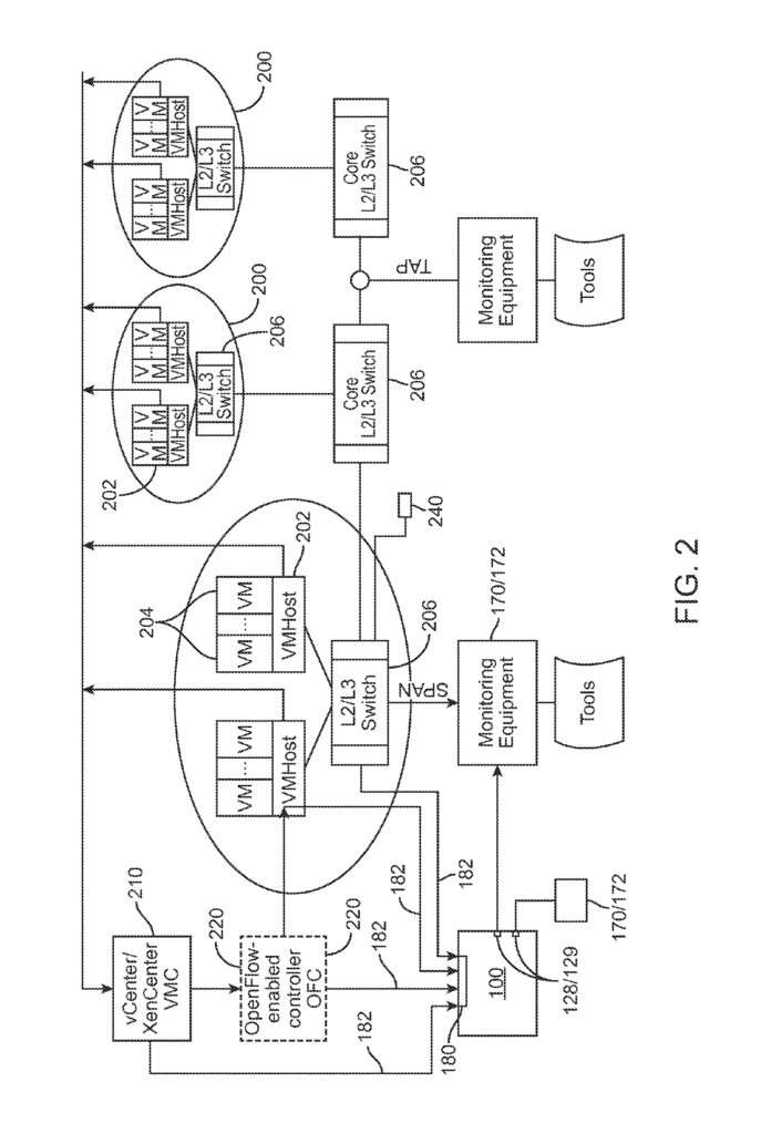
In some embodiments, as discussed above, the port180 at the network switching device 100 is configured in order to receive information 182 about a virtual network. Information 182 can be received by one or more devices. FIG. FIG. 2 shows an example of a deployment environment for the network switch 100. The figure shows that the network environment is divided into multiple sub-networks, each of which may contain one or more hosts 202 (e.g. VM host). Each of the hosts 202 can also include one or multiple workloads (e.g. virtual machines) 204.
In some embodiments, port 180 of the network switch device may be configured to accept the information 182 about the virtual network either directly or indirectly from host(s)202. In other embodiments the port 180 of the network switch device may be configured to directly or indirectly receive the information 182 about the virtual network from a switch (206), to which the hosts 202 are communicatively connected. In different embodiments, the switch 206 can be an L2/L3 or other type of switch. In one implementation, port 180 can be configured to snoop on signaling traffic that is used to map VM hosts with VM targets, to discover the VM host, or to create the VM target. In VXLAN technology, IP Multicast can be used to send ‘ARP-like’ packets in order to locate the host hosting a specific VM target. In certain network virtualizations, such as VXLAN where signaling messages are used to set up the tunnel data, these signaling message may be snooped by the L2/L3 switches 206 for reception by network switch devices 100 in order to obtain tunnel information without involving a database (e.g. a vCenter or a XenCenter). Or an OpenFlow controller.
Click here to view the patent on Google Patents.
Leave a Reply