Invented by Jill Bares, Christopher Daute, Jonathan Tallon, Gregory Bodden, Emanuel Gagliardi, API Healthcare Corp
Time and attendance tracking systems are software applications that allow employers to monitor their employees’ work hours, attendance, and other related data. These systems can be used to track employee time and attendance in real-time, which can help businesses to manage their workforce more effectively. This can also help to reduce errors and inaccuracies in payroll processing, which can save businesses time and money.
There are several types of time and attendance tracking systems available in the market. Some of the most popular ones include biometric systems, RFID systems, and mobile apps. Biometric systems use fingerprint or facial recognition technology to track employee time and attendance. RFID systems use radio frequency identification technology to track employee movements within a workplace. Mobile apps allow employees to clock in and out using their smartphones.
The market for time and attendance tracking systems is expected to grow significantly in the coming years. According to a report by MarketsandMarkets, the global market for time and attendance tracking systems is expected to reach $5.3 billion by 2024, growing at a CAGR of 9.5% from 2019 to 2024. This growth is driven by the increasing adoption of cloud-based time and attendance tracking systems, which offer several benefits such as scalability, flexibility, and cost-effectiveness.
One of the key drivers of the market for time and attendance tracking systems is the need for businesses to comply with labor laws and regulations. Many countries have strict labor laws that require businesses to accurately track employee time and attendance. Failure to comply with these laws can result in hefty fines and legal penalties. Time and attendance tracking systems can help businesses to comply with these laws and avoid legal issues.
Another key driver of the market for time and attendance tracking systems is the increasing demand for remote work and flexible schedules. With more employees working from home or on flexible schedules, it has become more challenging for employers to monitor their work hours and attendance. Time and attendance tracking systems can help to address this challenge by providing real-time tracking of employee time and attendance, regardless of their location or schedule.
In conclusion, the market for system and method to track time and attendance of an individual at a workplace is growing rapidly, driven by the increasing need for businesses to accurately track employee time and attendance. With the rise of remote work and flexible schedules, time and attendance tracking systems have become essential tools for businesses to manage their workforce effectively. As the market continues to grow, we can expect to see more innovative solutions and technologies being developed to meet the evolving needs of businesses and employees.
The API Healthcare Corp invention works as follows
A system and method for tracking time and attendance at a work place is provided. The system comprises a location tracker that detects the presence of the portable electronic device, a clocking system that records the clock-out time of the individual in the workplace and a controller. The main controller will receive an electronic communication indicating that the portable device is in a non-work or break area. If it does not detect the recording of the clock-out time by the time clock system and the main controlesr, the device will automatically send an alert to the user.
Background for System and Method to Track Time and Attendance of an Individual at a Workplace
The statements in this section are merely background information relating to the disclosure, and may not be considered prior art. Employee time clocks, whether mechanical or electronic punch clocks, are typically used at work to help employers track the time employees have worked. The time clock system records the date and time of the employee in order to create a record that can be used by the payroll department to calculate the correct pay. Known time clock systems use biometrics to verify an employee’s unique identity, such as fingerprints or retina scanners. Despite this, the current time and attendance system still requires significant time and expenses from supervisors or managers to review time clock transactions, such as clocking in and out, to ensure compliance with rules and regulations and work schedules. “Known attempts to cut this cost have only focused on employee training and discipline.
The above-recited concerns have led to the need for a time-and-attendance system and method that monitors in real-time employee presence, compliance with the recording or registration of a logout on the time clock, and automatically triggers an electronic communication of alert, so as reduce payroll review, corrective action, and human intervention, while maintaining employer-employee trust. “The embodiments of this subject matter address the above-described need.
According to an aspect of the subject, a system is provided to track an individual’s attendance and time at work. The system comprises a location tracker that detects the presence of a portable device carried by an individual, a clocking system that records the clock-out time of the employee at the workplace and a controller. The main controller will receive an electronic communication indicating that the portable device is in a non-work or break area. If it does not detect the recording of the clock-out time by the time clock system and the main controlee, the device will automatically send an alert to the user.
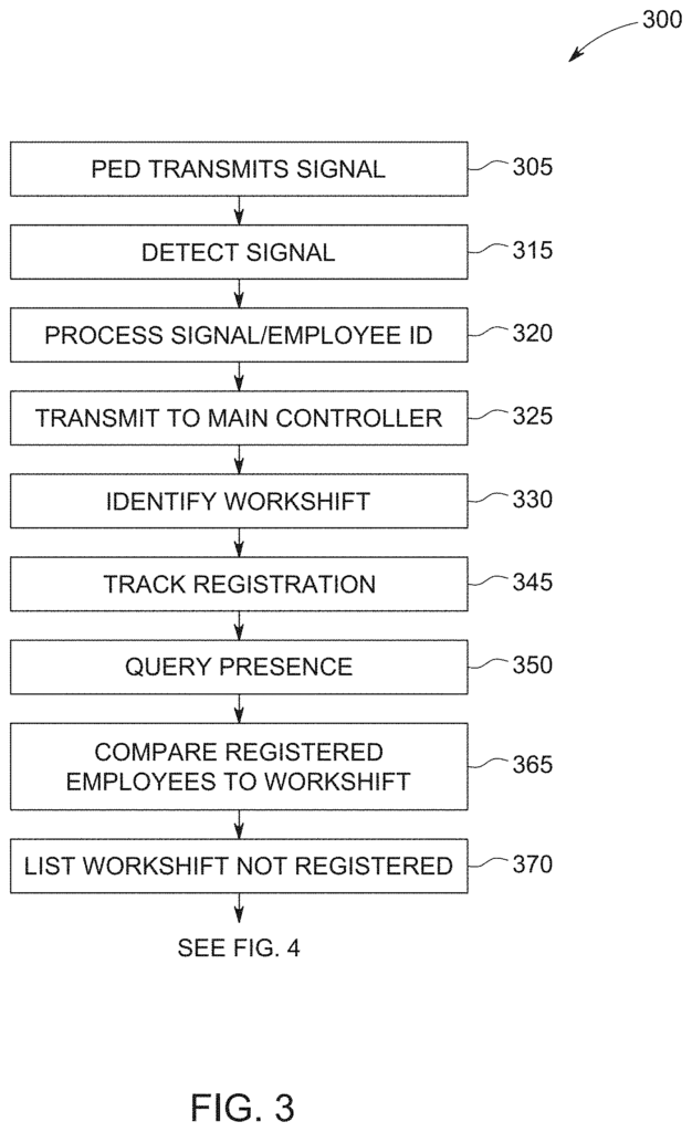
The method comprises the steps of: detecting via a wireless reader a location data indicative of a presence of a portable electronic device uniquely associated with and carried by an individual, the portable electronic device including a first microprocessor connected to an interface; detecting a clock-out registration time of the individual at a time clock system; storing information data of a scheduled workshift database of a predefined area of workplace for a schedule workshift file of that individual. The method includes the following steps: detecting, via a wireless read, a location data indicative a presence of an individual’s portable electronic devices, each of which has a microprocessor and interface connected; detecting the clock-out time of an individual at a system of time clocks; storing information data for a schedule workshift file and a predefined area at a database of workshifts, where the information data comprises a workshift period, an end-time, and intermediate break times between the
This summary is intended to describe briefly aspects of the subject described below in Detailed Description. It should not be used to limit scope of subject matter disclosed in this disclosure.
The following detailed description refers to the accompanying drawings, which form a part of this disclosure. In which are shown specific examples that can be practiced. These examples provide enough detail for one skilled in art to practice the subject matter. It is also to be understood that additional examples can be used and that logical and mechanical changes as well as electrical modifications may be made to the disclosure without departing from its scope. This detailed description does not limit the scope of this disclosure. It is intended to illustrate an example implementation. You can combine features from different parts of this description to create new aspects of subject matter.
When introducing the elements of different embodiments of this disclosure, the articles are?a? ?an,? ?the,? The words ‘the,? The words?said’ and?comprising,’ are meant to indicate that one or more elements are present. The words?including,? ?including,? The words ‘including,? The words?including’ and?having’ are meant to be inclusive, meaning that other elements may exist in addition to those listed. Users and/or their plural forms are used as a general term to refer to anyone who can access, use, or benefit from the disclosure. When the phrase “at least” is used in this document, it means that there are no limits. The phrase?at least? “Open-ended
In the following detailed description it is made reference to the accompanying illustrations that are a part of this document, in which specific embodiments can be illustrated and practiced. The embodiments have been described in enough detail for those who are skilled to use them. However, it should be noted that other embodiments can be used and that changes in logical, electrical, mechanical and other aspects may be made to the embodiments without departing from their scope. This detailed description should not be interpreted as a limitation.
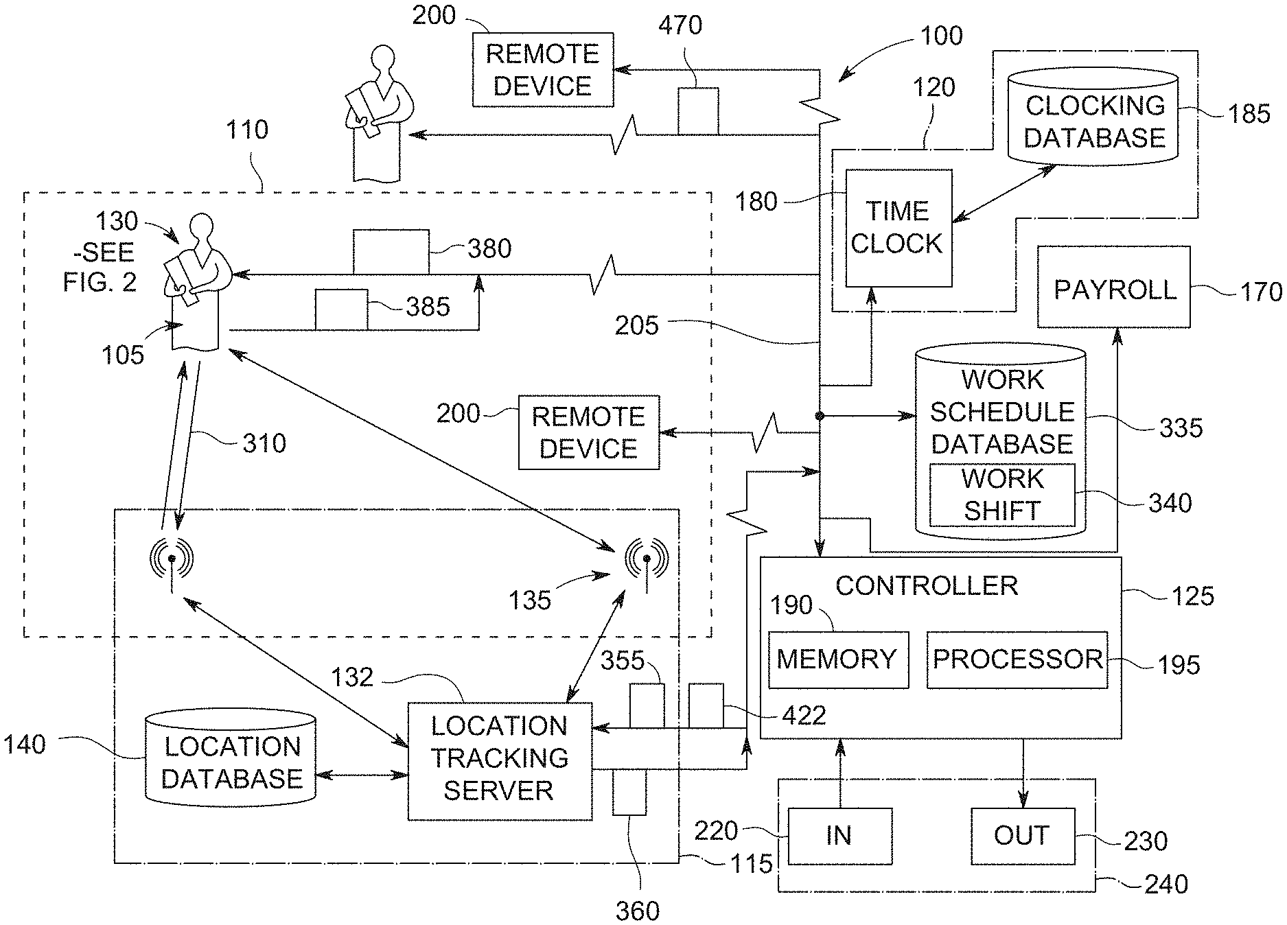
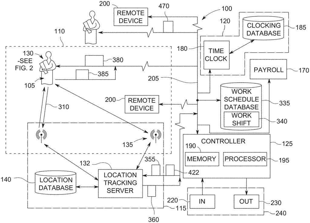
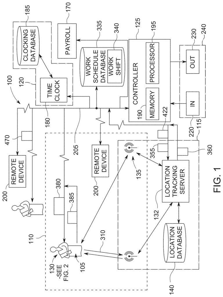
FIG. The system 100 shown in FIG. 1 is a particular embodiment that tracks the time and attendance of an employee 105 within a defined area 110 at a workplace. The system 100 comprises a location tracking 115 and a clock system 120 that are in communication with the main controller 125. The individual 105 could be an employee at the workplace, a consultant, contractor, or any other third-party person. “This is not intended to limit the subject matter of this invention.
The location tracking system can be used to track the presence of a portable device 130, carried by an individual 105 in the predefined workplace area 110. This is done electronically and in real time. A location tracking system 115 may include a computer server or main location tracking computer 132 that is in communication with a stationary device 135 (e.g. a transceiver), which can communicate with the portable device 130 carried by the individual 105. Location tracking system 115 may employ various wireless technologies (e.g. optical, radio frequency, bar code scanning and ultrasound, GPS, wireless local area network, wireless high frequency, ultra-wideband (UHF), Bluetooth?, Zigbee?, Wi-Fi?, cellular positioning, etc.). The subject matter of this invention is not limited to any particular wireless technology (or combination thereof) for tracking the location of portable electronic devices 130. The location tracking database 140 can be included in the location tracking system or connected to it via other means. This allows the location tracking database 140 to record or store the collected location data that is acquired by the location tracking device 115 or received therefrom.
![]()
Referring to FIG. The location tracking system can detect or track the presence of the portable device 130 in general. The portable electronic device can be in the form or a badge or tag, mobile or cellular phones, etc. The microprocessor 150 is connected to the interface 150. Interface 150 can be composed of various input devices that are generally able to receive the instructions sent by the individual to the main control, and an output device which is generally able to show feedback from the main control to the individual. Input devices can include keypads or selector buttons (mechanical or touch-activated) that, when activated, instruct the portable electronic device to send instructions to the main control 125. In FIG. The keypad 155 includes an acknowledge selector 157 and a decline selection button 159. A visual indicator 160 can be used as an example (e.g. LCD screen, LED lights, etc.). Or an audible indication 165, or a combination thereof, that can be used to communicate feedback from the main controller or message content in electronic format.
Referring to FIG. The time clock system can be configured to record or track a date, a clock-in or clock-out, or both, associated with an individual’s unique identifier. The time clock 120 can be configured to convert information pertaining to the transactions of the individual 105 in relation to clocking-in (i.e., registration with time clock 120 to record the start of work), or clocking-out (i.e., registration with time clock 120 to record the end of work), at the timeclock system 120, into an electronic format that is then communicated to other systems 170 to develop accounting records, generate payrolls, etc. The time clock system can communicate wirelessly or hardwired with other components of the system 100. The time clock 120 can have an internal clock to track the current date and time and readers or scanners to read data from individual identification cards, tags or badges. The time clock 120 can also include a local screen 180 that displays a transaction category (e.g. clock-in, out, etc.). The clocking database can store and retrieve the current time, date and unique individual identifier for time and attendance as well as the associated unique individual identifier. The time clock 120 can also use other technologies, such as facial recognition, finger print scanning, retina scanning and the like, to verify that the unique identification is associated with the action of an individual 105. “This patent is not limited to the subject matter described in this document.
The main controller 125 is generally capable of receiving, processing, and transmitting information via electronic communications from and to the location tracking system 120 and time clock system 115. The main controller 125 example can include a memory having a set of computer-readable program instructions that are executed by a processor 195. The memory 190 of the example can be a computer-readable medium, which is non-transitory and tangible. It stores electronic data and information, and program instructions that are accessible to and readable by a computer processor. The memory 190 may be accessible via a network connection by a remote computing system 200 or a portable electronic device carried by an individual or supervisor 105.
The computer-readable instruction can include a programming code to be executed by the computer processor. The software code may be stored in the memory 190, either independently or in conjunction with other software such as firmware or dedicated hardware. The computer program product can be integrated into the main controller 125 or stand alone. The term tangible, nontransitory computer-readable storage medium is used in this document to define any type of computer-readable storage device or storage disk, and exclude propagating signals and transmission media. The term ‘tangible, nontransitory computer-readable storage medium’ is used in this document. As used herein,?tangible non-transitory computer readable storage medium’ and?tangible machine readable storage media? “The terms can be interchanged.
The memory 190 may include, but is not limited to: random access memory (RAM), Read Only Memory (ROM), Synchronous dynamic random Access Memory(SDRAM), Dynamic RAM (DRAM), flash memory, a caching device, optical storage (CD, DVD, etc. ), magnetic cassettes, tapes, magnetic disks or other magnetic storage devices; a hard drive or flash memory.
The example computer processor can include hardware that executes one or more tasks defined by computer-readable program instructions. Computer processor 195 may be part of, for instance, a server, laptop, desktop, mobile device, such as a cell, smart, or tablet, like an IPAD. The computer processor 195 can be, for example, part of a computer server, a laptop or desktop (e.g. cellular phone), a tablet such as an IPAD? The computer processor 195, for example, can be implemented with one or more integrated or logic circuits, controllers, microprocessors, or controllers of any desired manufacturer or family.
The memory 190 and the computer processor 195, as described herein, can be standalone or integrally constructed in various programmable computing device of various types. For example, a cache or hard drive for a desktop or laptop computer, FPGAs, application-specific integrated systems (ASICs), ASSPs, system-on a chip systems (SOCs), PLDs, etc. Or the like, and any combination thereof, operable to implement the instructions associated with implementing a method (discussed below) of the subject matter discussed herein.
The controller of the system 100 may also be configured to send and receive instructions from remote computer devices 200. As referred to herein, remote computer devices can be a mobile phone, a computer of any type (desktop or laptop), a Personal Digital Assistant or mobile device, a notebook or tablet or another mobile computing device or a combination thereof. This description can be implemented either as a standalone computer program or as an app configured to run on one or more remote computing devices 200. The application (e.g. webpage, applet, or other mobile executables) can generate various displays or graphics/visual representations as described herein, such as graphic user interfaces.
The network 205 facilitates the transmission of digital or electronic data. The network 205 example can be a wired connection (e.g. a USB 2.0 or 3.0 connection, data bus, etc.). Wireless interfaces (e.g. radio frequency, optical, infrared or near-field communication (NFC)) are also possible. A wide area network, a local network, the Internet, a cloud computing infrastructure consisting of computers, routers and servers, gateways etc. Or any combination of these that allow the system 100 to communicate with different computing devices 200.
In the case of the example network 205, which includes a cloud-based architecture, the system can share information through web-based apps, cloud storage, and cloud services. A web-based portal, for example, may be used to provide access to information. The system 100 may illustrate the Web portal as the central interface for accessing information and applications. Data can be viewed, for instance, through the Web portal or viewer. The Web-based Portal can also be used to manipulate and spread data, for example. The Web-based Portal can be accessed locally (e.g. in an office), and/or remotely, (e.g. via the Internet or other network or connection 160).
The main controller can also communicate with an input device or device 220, and an output device or device 230. The input device 220 can be a keyboard or joystick, a mouse, a touch-screen, wands, light trackers, or other input devices. The output device 230 can be a liquid crystal monitor, plasma screen, cathode-ray tube monitor or touch-screen. It could also include a printer, an audible device, a printer with a touch-screen and a printer. The input device 220 can be independently of the output device 230, or combined as an interface 240 for the system 100.
Click here to view the patent on Google Patents.