
Invented by Chung Chun Wan, Choon Ping Chng, Google LLC
In response to this, a new trend has emerged in the market for VR HMDs ? devices with a reduced number of cameras. These devices utilize advanced algorithms and sensors to achieve accurate tracking with fewer cameras, making them more affordable and user-friendly. This article will explore the market for VR HMDs with a reduced number of cameras and the methods used to operate them.
One of the key players in this market is Oculus, a subsidiary of Facebook, which introduced the Oculus Quest 2. This device features a single front-facing camera, along with additional sensors and algorithms that enable accurate tracking of the user’s movements. The Quest 2 has gained significant popularity due to its affordability and ease of use, making it accessible to a wider audience.
Another notable player in this market is HTC, which released the Vive Cosmos Elite. This device utilizes a combination of inside-out tracking and external base stations to achieve precise tracking with only four cameras. The Vive Cosmos Elite offers a high-quality VR experience while reducing the complexity and cost associated with a larger number of cameras.
Methods for operating VR HMDs with a reduced number of cameras vary depending on the device. Some devices utilize inside-out tracking, where the cameras are embedded within the HMD itself, allowing for a more portable and user-friendly experience. These cameras capture the user’s surroundings and track their movements without the need for external sensors or base stations.
Other devices, like the Vive Cosmos Elite, combine inside-out tracking with external base stations. These base stations emit infrared signals that are picked up by the HMD’s cameras, allowing for even more precise tracking. This hybrid approach offers a balance between accuracy and convenience, as it eliminates the need for complex setup while still providing a high level of tracking accuracy.
The market for VR HMDs with a reduced number of cameras is expected to continue growing in the coming years. As technology advances, we can expect to see even more innovative solutions that further reduce the number of cameras required for accurate tracking. This will make VR more accessible to a wider audience, as the cost and complexity associated with traditional camera-based tracking systems are reduced.
In conclusion, the market for VR HMDs with a reduced number of cameras is expanding rapidly, driven by the demand for more affordable and user-friendly devices. Companies like Oculus and HTC are leading the way with their innovative solutions, utilizing advanced algorithms and sensors to achieve accurate tracking with fewer cameras. As this market continues to evolve, we can expect to see even more advancements that make VR accessible to a wider audience.
The Google LLC invention works as follows
Herein are described examples of virtual-reality headsets with reduced number of cameras and their operating methods. The disclosed example method involves providing a VR head-mounted display with an imaging sensor that includes color-sensing and infrared sensing pixels. It also includes capturing an image using the imaging device, which has a color and IR part. Forming an IR from some of the IR part of the captured image, performing a tracking based upon the IR image, forming a colored image by replacing at least some IR data with color data derived from the color portion in the image, and the location of the IR pixels removed, and IR pixels.
Background for Virtual reality head-mounted device with reduced number of cameras and methods for operating same
Virtual-reality head mounted displays use multiple cameras to render and/or image virtual-reality environments where someone is physically or virtually present. They also track the movements of viewers and/or items that are physically and/or virtual present in the virtual reality environment.
Virtual-reality head mounted devices or displays with reduced number of cameras and methods for operating them are disclosed. A disclosed example method comprises providing a virtual reality head-mounted display with an imaging sensor that includes color-sensing and infrared sensor pixels. Capturing an image using the imaging sensors, the sensor having color-sensing and infrared sensor pixels amongst them; forming an IR image from atleast some of infrared part of the image, performing a tracking based upon the IR image, forming a colour image by replacing atleast some of removed in
The disclosed example virtual reality head-mounted device is used in a virtual environment. It includes an imaging sensor that captures an image with color-sensing and infrared pixels. A reconstructor removes at least part of the infrared portions from the image to create an infrared version.
The disclosed example non-transitory computer-readable media contains machine-readable instructions which, when executed, cause the machine to: provide a virtual reality head-mounted display with an imaging sensor; capture an image having both a color and infrared portions; form an infrared picture using at least part of the portion; perform first tracking using the infrared picture; form a colour image by replacing at least part of the portion of infrared in the image with color data determined based on at least the color portion, color portion, and the a
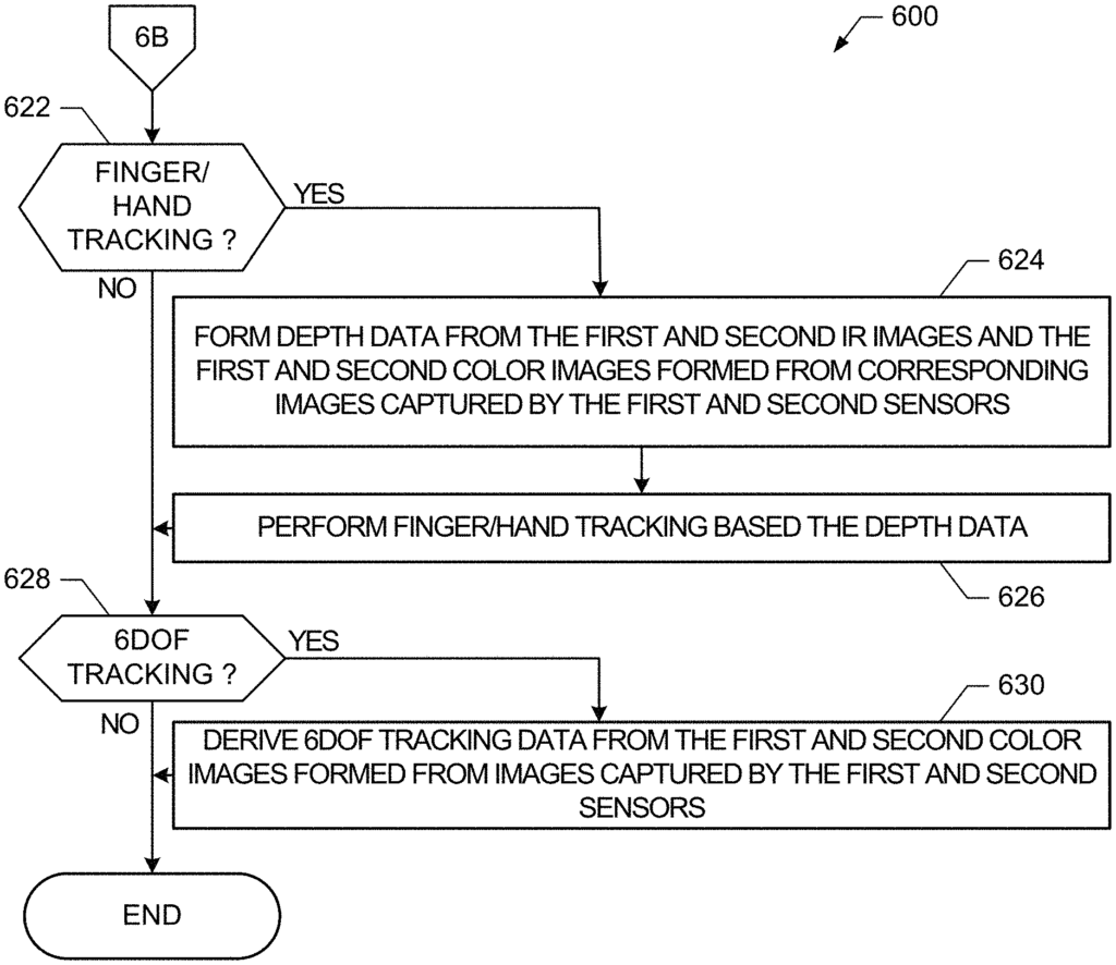
Virtual-reality head-mounted devices or displays (V-HMDs), are next-generation computer platforms that provide virtual reality environments and/or systems. A V-HMD may include several subsystems such as a camera, display, image processing, controller, etc. Camera and image processing systems are needed to perform a variety of VR functions, including those that meet the expectations of customers, users, and wearers. Examples of VR functions include but are not restricted to 6DoF head tracking, finger/hand track, depth sensing or environmental awareness, passing through images for display in or via the V-HMD or tracking a VR Controller or other device held or used by a user. V-HMDs require dedicated cameras for each VR feature. As an example, the first and second cameras are used for head tracking. The third and fourth cameras are used for finger/hand trackers. The fifth camera is for environmental sensing, such as depth. Hence, V-HMDs today can need nine or more cameras in order to perform this basic set VR functions. It is difficult to overcome the fact that V-HMDs require so many cameras. Weight, size, industrial design and other factors are crucial. Weight increase, size gain, cost increase and number of components can all be important. Other factors include decreased reliability, increased design complexity, industrial design restrictions, etc. The cameras are usually different from the other cameras in a VHMD, such as their size, resolution, and angle of view. These issues are further compounded by future needs for more VR functions. The number of cameras will reduce the amount of VR functionality that can be achieved, and thus make a VR-HMD more attractive on the market. There are still significant obstacles in V-HMDs to overcome in order to meet market needs that cannot be met with conventional VHMDs. V-HMDs’ ability to support a wide range of VR functions shows that there is still a great need.
Herein are examples of V-HMDs which overcome these problems. These examples use fewer cameras than the nine (9), namely two (2) instead of nine. However, they still provide at least the same VR functions as described above. The cameras and imaging sensors are designed to provide a wide range of imaging capabilities with fewer cameras. A camera example can be designed for a range of capabilities, such as a wide field of view, maximum or minimum sampling rate, required pixel arrangement etc. To realize the desired VR functions. As an example, the output of a wide-angle imaging sensor disclosed herein may be cropped into a mode, a normal or a narrow image. field-of-view image. Accordingly, using a wide-angle camera, in accordance with this disclosure, data can be captured to simultaneously or sequentially realize a small, normal, and/or wide field of view. The super-set addresses or provides all VR functions. Cost, complexity, weight etc. are not an issue because the super-set is a collection of capabilities. The conventional V-HMD can be used to implement a wide range of VR functions. The ability to support a greater number of VR features using just a pair stereoscopic camera provides an important new advantage in the VHMD market. An imaging sensor with its associated camera can be designed to provide a wide-angle of view to accommodate the required angle-ofview. The image data from this angle-ofview could then be extracted (cropped), to obtain a normal-angle-ofview. The camera(s), then, can be seen as being able support the requirements of two or more VR features. A camera or its image sensor is designed so that the data required for each supported VR function are obtained by processing the images in a respective manner. According to the disclosure, multiple VR functions can be achieved using just a pair cameras. This is a reduction of 75% in the number of cameras required. The two-camera configuration described here may be used to support other functions, past, present or in the future.
The following examples are non-limiting and illustrated in the drawings. In the following examples, we will refer to the drawings where like reference numbers refer to similar elements. The corresponding descriptions are not repeated when like reference numbers are shown. Instead, the reader is directed to the previous figure(s) that were discussed for the description of like elements. The attached drawings do not show these examples, variants, and portions thereof at scale, in specific shapes, and with specific relative measurements, as those are not relevant to the disclosure. They may also make it more difficult to understand the drawings. Certain elements may have intentionally been exaggerated to facilitate discussion. The drawings were drawn to aid in understanding and clarity. The arrangement of couplings and elements can be changed, rearranged etc. According to other implementations and claims of this disclosure.
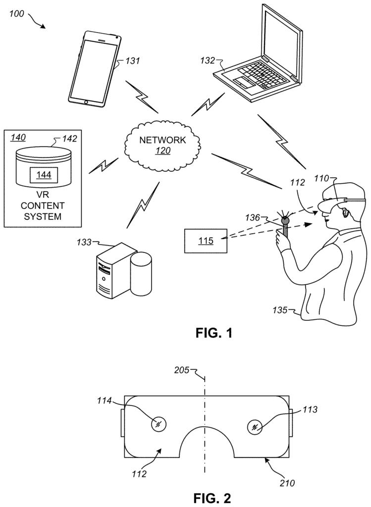
Turning the FIG. A block diagram for an example VR system is shown in Figure 1. According to the disclosure, an example VR system 100 has a VHMD 110 with a front surface 112. As shown in FIGS. As shown in FIGS. The cameras 113,114 can be placed at the same distance apart as the eyes of a person so that if two pictures are taken they can give a stereoscopic effect. In FIG. In FIG. 3. The cameras 113 & 114 can capture an area of light that is moving towards or contacting the face 112. The light may move in different directions or trajectories toward the face 112. The positions of the cameras 112 and 113 can be altered based on a variety of design parameters. The distance between the cameras can affect the depth of field. The selection of the V-HMD 110 may be based on several factors, including desired size, industrial design and use of additional cameras. Upgrades can include additional and/or alternate cameras to support, e.g. new VR functions. A fish-eye lense, for example, could have not been included at first, but later installed to support newly envisaged VR functions. One or more cameras 113 and 112 may also be controlled selectively to capture different locations at various times. The cameras 113, 114 do not have to be identical. A camera 113 or 114 can be updated, for example, by an end-user or service center, to support new V-HMD features and/or modify or customize the functionality of a VHMD. A VR controller 136 can be used by a user 135. This will be explained in more detail below. The VR controller can emit or reflect infrared light (IR) and/or any other type of light which can be detected by the cameras 113 or 114. This can help to determine the position of, for instance, the user’s hand. Other elements 115 of the VR system 100 may also emit or reflect IR light or any other type for tracking purposes or other VR applications.
In general the example VR system provides a virtual environment and VR content which can be accessed and viewed. The following description will relate to FIG. The example V-HMD can be implemented with only two cameras 113 and 114, as opposed to a larger number of cameras that is needed in conventional VHMDs.
As shown in FIG. The example VR system 100 comprises a plurality computing and/or electronics devices that are capable of exchanging data via a network. Devices can be clients or servers and communicate over the network 120, or via any additional or alternative networks. Examples of client devices include but are not restricted to a mobile device (e.g. a smartphone), a personal digital assistance, a portable music player, etc. A desktop computer 133 or laptop 132 can be used as a V-HMD 110. Other devices include a tablet electronic, a netbook or laptop 132, cameras, a desktop PC 133 or gaming device. The devices 110, 131-133 can be client devices. In some examples the devices 110 and 130-133 can include one or multiple processors, one or several memory devices that can execute client operating systems and client applications to access, control and light-emitting VR content on light-emitting portions devices implemented with each respective device. One or more devices 110 and/or 131-133 may emit infrared light (IR) and/or other types of light which can be detected by the cameras 113 or 114. This can help determine the position of the user or devices 110,131-133 to perform tracking or other VR functions.
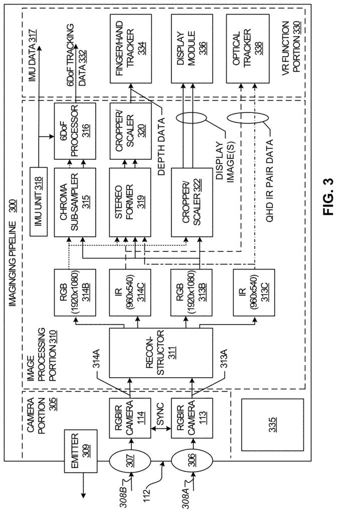
FIG. 1 shows an example of stereoscopic placement for the cameras 113 & 114. 2. In the example shown in FIG. The cameras 113 & 114 are equally separated from opposite sides of virtual dividing line (205), and are positioned at the same distance from the bottom of the face 112 “Other camera configurations that reflect other implementation objectives, or desired VR functions can be considered.
Turning to FIG. A schematic diagram of a possible imaging pipeline 300, which can be used in conjunction with any of the V-HMDs shown. The imaging pipeline 300, as discussed below can also be used for other non-imaging functions 335. The imaging pipeline includes a camera part 305, which includes the cameras 112 and 114. An image processing part 310 forms the images necessary for VR tracking functions. In some cases, there may be other portions 335, that perform other imaging and/or other non-imaging functions. FIG. FIG. Details such as caches, memory, busses, etc. have been omitted for clarity and to make the illustration easier to understand. These details have been omitted for clarity and ease of understanding.
The example camera portion 305 in FIG. The cameras 113, 114 and their respective lenses 306 or 307 are shown in FIG. The orientation of FIG. The light 308A, 308B, moving from left-to-right, passes through lenses 306, 307. Lenses 306, 307 may have optical effects that are performed, and impacts on the RGIBIR sensors of the cameras. The lenses 306 and 307 can be fixed or have variable apertures and depths of field. They may also have variable focal lengths. These functions can be performed automatically, manually or in a combination.
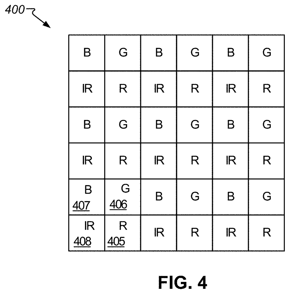
The R G and B pixels can be fitted with a per pixel IR-cutter so that a pixel will not respond to IR light. A dual-band filter, which passes only visible and IR light in a narrow band, can also be used to place inside the camera module so that the R G B pixels will only respond to light. IR sensing pixels will only detect narrowband IR, while R, B, G, and C pixels 405-407 will only detect R, B, G, and C visible light. The color image of the R G B sensing pixel 405-407 is improved compared to not having an IR cut filter per pixel on top. This is because there’s no IR light leaking into the R G B sensing pixel 405-407.
In some cases, the camera part 305 may include an IR emitter 309. The example IR emission 309 can be operated or activated selectively to emit IR lights that can reflect from objects, such as the examples objects 115 and 136. The reflected IR can be used to find the objects 115 and 136. The IR emitter 309 can be used separately or in addition to the V-HMD.
The example image processing component 310 in FIG. The RGBIR images 313A and 314A taken by the respective cameras 113,114 are sent to a reconstructor 311, The reconstructor 311 is able to create RBG images 313B, and IR images 313C, and 314C from RGBIR images provided by cameras 113, 114.
As shown in FIG. As shown in FIG. The IR pixels of a full RGBIR array 500 can be collected into a smaller array 550 that only contains IR pixel values. In FIG. Three examples of IR pixels from the image 500 to the image 550 are shown in FIG. Other IR pixels may be collected or moved in a similar way.
The RGB images can be created by removing or extracting the IR pixels in an RGBIR image. The array values where the IR pixels are represented can be changed to NULL or vacant as they are extracted. Value or indicator. In some cases, it is not necessary to modify the IR pixels as they can later be overwritten by image processing. In the case of FIG. In the example of FIG.
The reconstructor 311 is able to create an RBG 313B or 314B image and an IR 313C or 314C image from the RGBIR images provided by the cameras 113 and 114. The reconstructor 311 fills in any blank or vacant IR pixel location with green pixel values. This results in a completed RGB 313B and 314B.
The four images 313B 313C 314B 314C of FIG. The reconstructor 311 is capable of generating, forming or creating images 313B, 313C, 314B and 314C. These can be adapted, changed, combined etc. To perform a variety of V-HMD and/or VR functions. The reconstructor 311 creates the images of 313B and 314B by combining the different processing done on the images of 313A and 314. This gives the impression that there were more than two cameras used to capture these images.
Click here to view the patent on Google Patents.
Leave a Reply