
Invented by Hyung Suk Kim, Young Sam Park, Hun Joo Hahm, Jung Kyu Park, Young June Jeong, Samsung Electronics Co Ltd
The Samsung Electronics Co Ltd invention works as follows
A backlight of a liquid-crystal display comprises a number of light emitting packages that are arranged in a grid and spaced uniformly apart. Each light-emitting diode pack includes one or multiple light-emitting diode chip and is designed so that the light generated by the light emitting chip is emitted horizontally. Reflectors are made up of a number of cells that are connected in a matrix. “Each of the unit-sized reflection cells has each of its light generating packages at its center, and reflects light from the light emitting device at its center in both the horizontal and vertical directions.

Background for Backlight unit for liquid crystal display
1. “1.
The present invention is a backlight of a LCD, more specifically a unit that can be used with a lower number of light emitting devices. It has a common structure applicable to LCDs of any size.
2. “2.
The light emitting diode is a semiconductor device that emits light in various colors. Its light source can be made up of compound semiconductors such as GaAs and AlGaAs. Other materials include GaN, InGaN, AlGaInP, GaN or AlGaInP. The LEDs are now more versatile with the introduction of three primary colors (red blue green) and a white LED, which is made from nitride, a material that has excellent physical and chemical characteristics. The LEDs can be used for a variety of applications such as the backlighting of a keyboard or liquid crystal display, as a signal light, or even a guide lamp on an airport landing strip. They are also useful in street lighting and other similar situations.
As a standard to determine the characteristics of LEDs, the colors, brightness, light intensity, and similar, can be used. These are determined by the compound semiconductor material for the LEDs and, secondarily, by a package for mounting the LED chips.
FIGS. “FIGS.
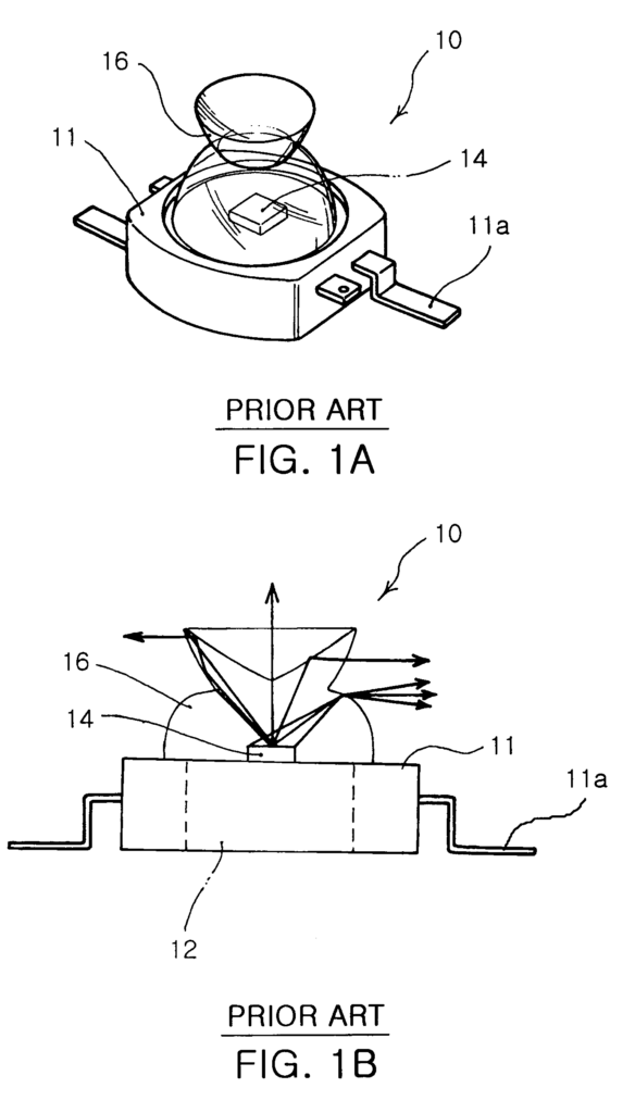
Referring to FIGS. “Referring to FIGS.
The lens 16 is a semi-spherical pyramidal shape that acts to refract the light from the LED chip 14, located in the middle of the top surface of the frame 11, to the horizontal direction.
The package structure consisting the frame 11 with the lens 16 is designed such that light emitted from the chip 14 is approximately horizontal, while heat generated by the chip 14 can be dissipated outside. This provides stable operation characteristics for the LED device 10.
The LED device 10 shown above is a source of spot light. To realize surface emission using the spot light sources, it is necessary to have a separate structure. In this regard, a structure has been provided whereby an LED array with multiple LED devices 10 in a row is mounted at the middle of a semi-cylindrical reflection plate. This allows surface emission to be realized through the reflective plate.
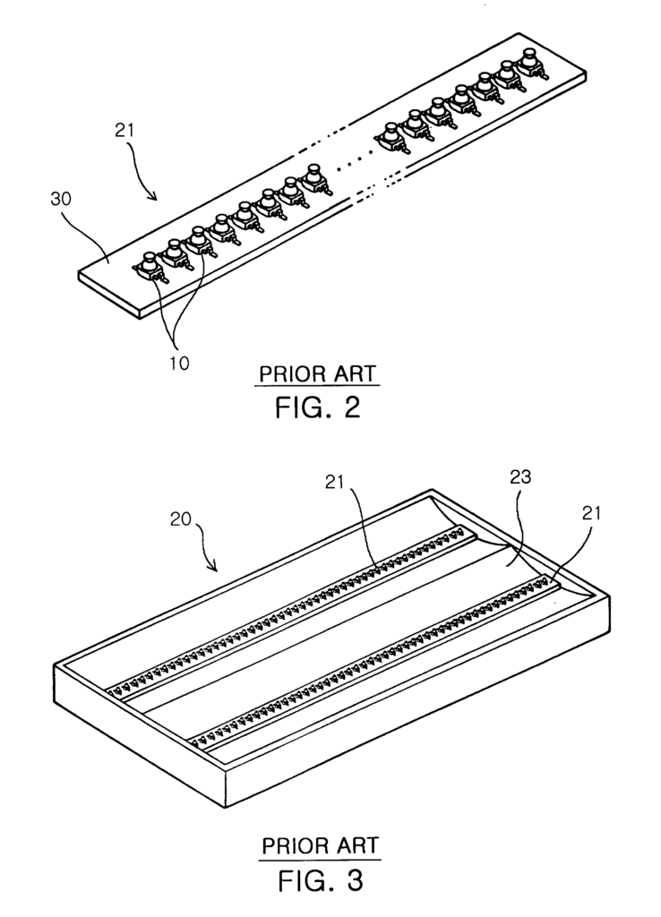

FIG. “FIG. The LED array 21 is shown in FIG. 2.
As shown in FIGS. The backlight unit 30 includes: as shown in FIGS. The LED array module 20 emits one color from red, blue, and green. A printed circuit board 21 has printed circuit patterns to transmit an electrical signal thereon, and is used for mounting the plurality LED devices 10 on the PCB in a row so that three colors are alternately emitted. The array module’s PCB 30 is made from Al which has a good thermal conductivity to improve heat dissipation.
The backlight unit 30 achieves surface emission on all ranges of a LCD screen, by reflecting the light emitted in the horizontal and perpendicular directions from the respective LED devices, mounted on the LED array 20.
The number of LED array modules required for the unit with the above-described structure is proportional to the size of the LCD screen that uses the LED modules. The number of LED devices 10 that are required for each LED array module 20 also increases in proportion to screen size.
The conventional backlight unit is a problem because the LED array module and the reflective plate must be redesigned to fit the LCD screen. Also, the number of expensive LED devices 10 increases in proportion to LCD screen size.
The LED devices 10 emit three colors, but since they are individually packaged and mounted on the PCB 21, the power is applied separately to each of them. This results in the three colors being mixed outside. In order to mix three colors from LED devices 10 properly, it is necessary for a mixing space to be provided, which results in a thick LCD screen.
Furthermore, because the LED devices 10 have been linearly arranged, the length of the LED module is determined by the size of the LCD screen. As the screen size increases, the number of LED devices 10 in one LED array 20 also increases. The expensive aluminum PCB 21, however, is also larger. The conventional LCD is inefficient in terms of manufacturing costs and the LED devices are not widely applicable because additional PCBs are required to match the size of the LCD.
Furthermore, the conventional LED device 10 refracts the light in the horizontal using the difference in refraction rates between the lens 13 and the other media. Due to the fact that the light from the center LED to the upper portion is not changed in direction, it can cause a hotspot at the center. A shadow sheet must be used for the backlight 30 to avoid this. The conventional backlight unit is also not competitive in price because it uses a structure of 1 chip per package, whereas the LED device only packages one chip.
The present invention was made to address the problems mentioned above. Its object is to provide a liquid-crystal display backlight that has a common structure applicable to all sizes of liquid-crystal displays and which can be constructed with a lower number of light emitting devices.
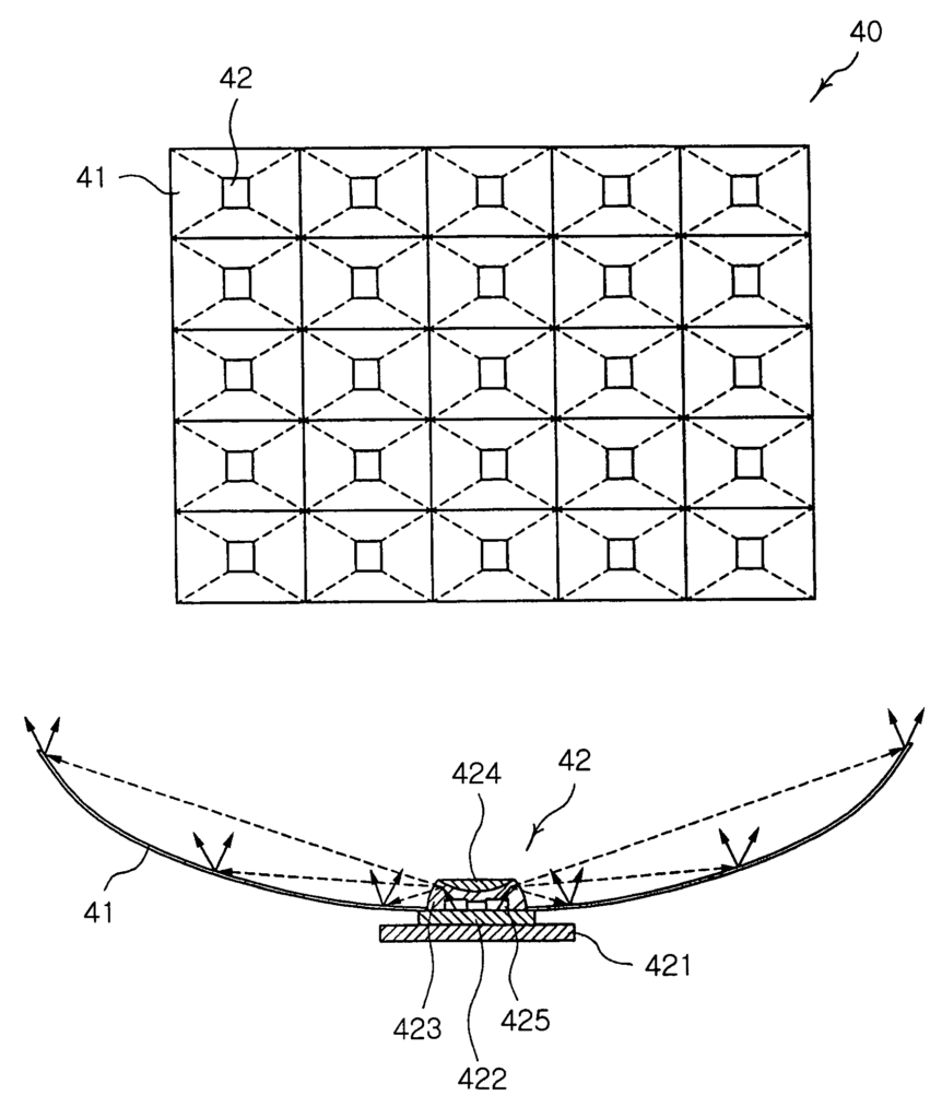
According to one aspect of this invention, these and other objects are achieved by a backlight of a liquid-crystal display that includes: a number of light-emitting diode packs arranged in a grid while being separated uniformly from each other; each light-emitting diode pack including one or multiple light-emitting diode chip and structured so that the light generated from those chips is emitted horizontally; and a reflective unit consisting of several reflection cells interconnected in a
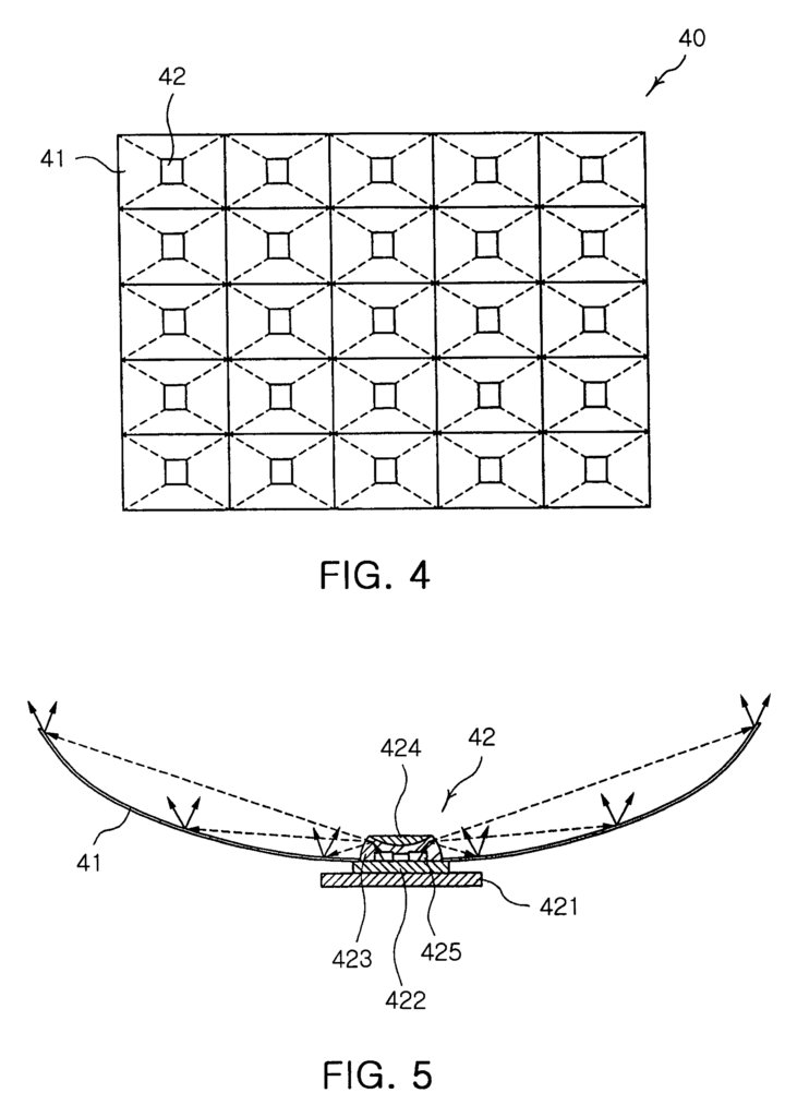

Further,” each of each of reflection cells of the reflector can be formed with a hole of a predetermined diameter at its center, and the light emitting package may be inserted in the hole.
Click here to view the patent on Google Patents.