Invented by Kevin J. Babich, Skywave Networks LLC
The Skywave Networks LLC invention works as follows
A communication system utilizes multiple communications links. Preferably, these links use different media. Multiple communications links can include a fiber optic cable with a high bandwidth and high latency link that is configured to transport large amounts of data, but has a high delay. These communications links can also include a low-latency/low-bandwidth link that uses skywave radio wave propagation to transport smaller amounts of data across a large portion of earth’s surface. Both communications links can be used to coordinate activities, such as buying and selling financial instruments.

Background for Communication method and system using low latency/low bandwidth and high data bandwidth/high latency pathways
Recent technological advances have improved communication across huge distances. Satellite and fiber optic networks allow remote areas of the globe to communicate. Fiber optic cables, which span across such vast distances as the Atlantic and Pacific Oceans can experience a time delay or round-trip delay of up to 60 msec. Satellite communications may experience even longer lag times. This high latency is often inherent to the communication medium or equipment. Light may travel 30-40% slower through an optical fibre than a radiowave traveling the same distance in free space. Multiple repeaters are often required for fiber optic networks, which increases latency. This high latency is not a problem in many circumstances but can create unacceptable delays when performing time-sensitive activities. This is especially true for activities that are complex in logic or depend on rapidly changing conditions. These latency issues can for example create problems for a whole host of activities, such as in the operation and/or synchronization of distributed computer systems, scientific experiments with geographically large sensor arrays, and telemedicine/diagnostic activities, to name just a few. For example, in order to buy or sell securities, or other financial instruments on world markets, the communications links are typically fiber optic cables, coaxial cable, or microwave communication link systems. “Any delays in executing orders, such as those caused by high latency over fiber optic lines, could lead to significant financial loss.
An innovative communication system and method was developed to address these latency issues, as well as others. The communication system transmits command data so that it is received by a receiving station prior to (or at the time of) receiving triggering data. The command data may include one or several directives, instructions or rules that are used to control a machine (such as a mechanical or computer device) in order to perform one or multiple actions. In one form, command data may include a program to buy and/or sell particular options or stock at certain prices, ranges and/or under other conditions. The command data is usually (but not always) larger than the trigger data, so that it takes more time to transmit the command data over communication links with the same bandwidth. The triggering data contains information that identifies one or more commands to be executed in the command data. The triggering data, for example, can identify one of more options in the command information that indicates the stock (or stocks) to be purchased at a certain price. In one example the command data may be transmitted via a high-bandwidth, high-latency communication link, like a fiber optic, while the triggering data could be transmitted via a low-bandwidth, low latency communication link, for instance, by using skywave propagation, which involves refracting or scattering radio waves in the ionosphere. This allows the relatively small triggering data to be received more quickly at the receiving station, compared to if it was sent over a high bandwidth and latency communication link such as fiber optic cable. This system and method reduces time for complex, time-sensitive tasks, such as financial transactions over long distances. This technique can be used in one form to perform remote actions beyond the radio horizon. For example, transatlantic communications. This technique is adaptable for two-way communications as well as one-way communications.
In one example, “This unique communications system and method uses multiple communication links.” In one form the communication links are different media. This system could be used to send a large number of preprogrammed rules or commands over a high-latency/high-bandwidth link, in advance of an event that triggers the system, such as a news report, market event, predetermined time and date, etc. The set of preprogrammed rules can be sent to a Field Programmable Gate Array as a firmware update or a software upgrade. “When a trigger event occurs, the triggering data can either be sent via a low-latency/low-bandwidth link or both, which will cause preprogrammed commands be executed as planned.
In one system example, the low-latency/low-bandwidth communications link transmits data using radio waves in conjunction with the high latency/high-bandwidth communications link. This could be a packet switch network that operates over fiber optic cables. This combination can include a variety of combinations, with vastly different differentials between high and low latency. Low latency links may transmit using high frequency (HF), radio waves over a path of propagation between North America, and Europe. For example, radio waves can transmit with a latency between 20 and 25 ms (40 to 50ms round-trip). “A higher latency link could carry data through a different propagation route, or possibly through a separate medium between the two continents, that may, for example, have a delay of 30 ms one-way or 60 ms both ways.
The system can also continuously monitor and use various HF bands in order to maintain the strongest signal between distant locations, depending on the solar and atmospheric conditions. This monitoring can include using third-party data or analyzing the results of experiments. These conditions are particularly important for the low-latency link, which can use skywave propagation as a relay to relay HF signals over long distances. Skywave propagation can be enhanced by repeater stations in the air or on the ground.
In another aspect of security, the overall system can be improved by sending a continuous stream of actions or triggering messages through the separate communication links in order to confuse malicious parties and discourage their attempts to intercept future transmissions and decipher them. The messages can be short or mixed in with other transmissions that may continue continuously or only for a short time, according to a schedule. Security can be improved by sending short messages on skywave propagation over one or several frequencies or by sending parts of a single message simultaneously on multiple frequencies. Other techniques can be used to improve security, such as encryption, hashing in two directions, etc., but this may cause additional latency on both links.
The detailed description and drawings provided here will reveal additional forms, objects, features, aspects, benefits, advantages, and embodiments of the present invention. The detailed description and accompanying drawings will reveal additional forms, objects and features of the invention.
To promote an understanding of invention principles, references will now be made in order to illustrate the drawings. Specific language will be used for the same. It is understood, however, that the scope of this invention will not be limited. As would be expected by a person skilled in the relevant art, any alterations or modifications to the described embodiments and/or further applications of principles of the invention are envisaged. The invention is described in detail in one embodiment, but those who are skilled in the art will understand that certain features may be omitted for clarity.
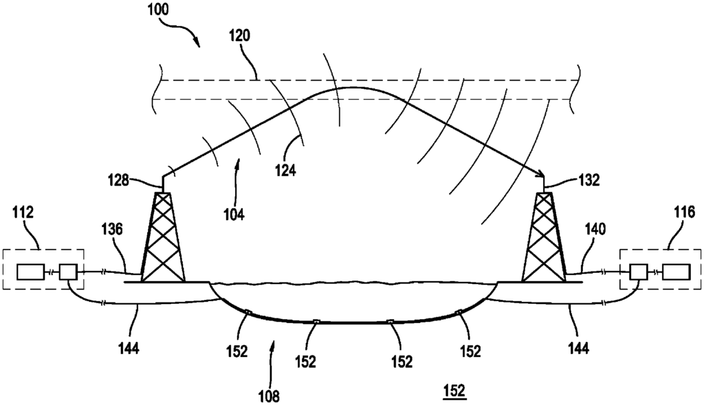
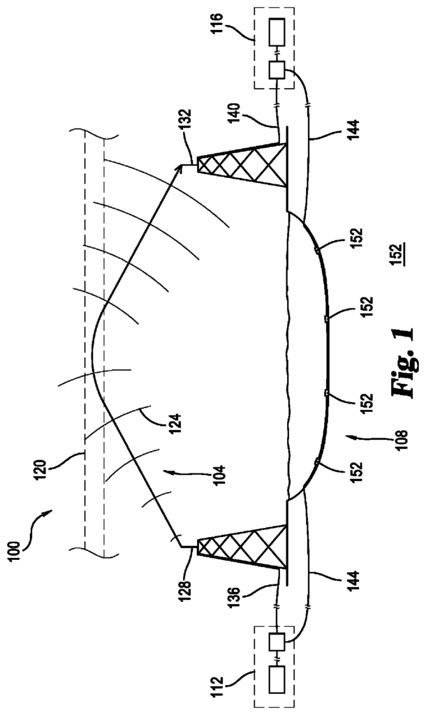
FIG. The figure 1 shows at 100 an example of a system that is configured to send data over a low-latency, low-bandwidth communication link 104 and separate data through a high-latency, high bandwidth communication link. Communication links 104 & 108 are separate connections that connect a first node of communication 112 to a second node of communication 116. Low latency connection (104), for example, can be configured to send data via electromagnetic waves 124 that travel through space using skywave propagation. A transmitter located in the first communication node 112 can generate electromagnetic waves 124, which are then transmitted along a transmission cable 136 to an external antenna 128, resulting in a low latency connection 104. Antenna 128 may radiate waves 124 when they encounter an ionized part of the atmosphere 120. The ionized part of the atmosphere 120 may refractively refract this electromagnetic energy, causing waves to re-direct towards the earth. The waves 124 can be received by an antenna 132 connected to the second communication node 116 via transmission line 140. As shown in FIG. As shown in FIG.
Data can also be sent between communication nodes 112 & 116 by using a high-latency communication link 108. As shown in FIG. As shown in FIG. As shown in FIG. Repeaters 152 may be used to increase the latency of a high-latency communication link, as shown in FIG. FIG. FIG. Transmission line 144 can also be without repeaters. The FIG. “Although FIG.

The configuration in FIG. The configuration shown in FIG. The second node is located geographically distant from the first node. This part of the Earth’s surface can include one or more continents or oceans or mountain ranges or other geographical areas. The distance shown in FIGS. The distances shown in FIGS. In an example, node node 112 in Chicago, Illinois, United States of America and node node 116 in London, England in the United Kingdom. Node 112 could be in New York City (N.Y.) and node116 in Los Angeles (Calif.), both of which are in North America. “Any combination of distance, nodes and links can be used to provide a satisfactory latency or bandwidth.
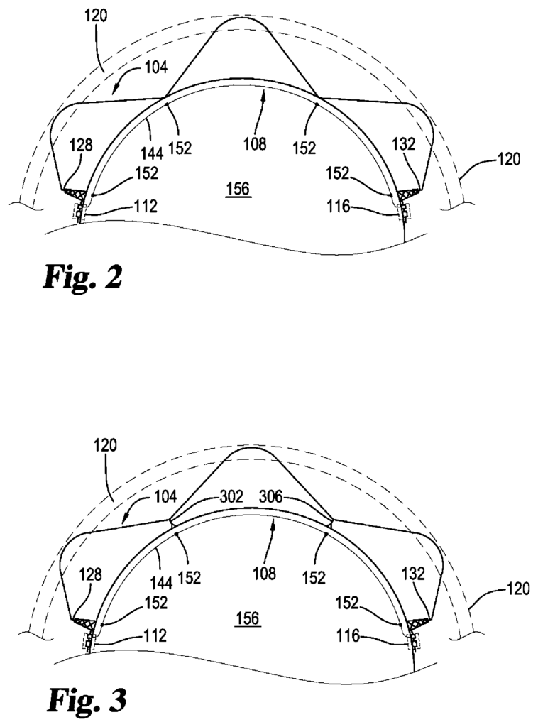
FIG. The skywave propagation allows for electromagnetic energy to travel long distances. Skywave propagation allows low latency communication links 104 to transmit electromagnetic waves into an ionized portion of the upper atmosphere 120, which refracts electromagnetic waves toward the Earth. The waves can then be reflected off the surface of earth, and then returned to the ionized upper atmosphere 120. They may be refracted again toward the earth. So electromagnetic energy can’skip’. The low latency and low bandwidth signals can be sent repeatedly, allowing them to cover greater distances than would otherwise be possible with non-skywave propagation.
The system shown in FIG. FIG. In FIG. Repeaters 302 or 306 can be used to enhance the skywave propagation discussed in FIGS. In this example, the first repeater 302 can receive low-latency communication signals from antenna 128. The signal may be refracted by the ionized area 120, and then returned to Earth where it may be received and retransmitted by repeater 302 via skywave propagation. Repeater 306 can receive the refracted signal and then retransmit it via antenna 132 to second communication node 116 using skywave propagation. In FIG. Any suitable number, configuration or positioning of the ground repeating station 302 can be considered. The number of repeaters may be increased to allow for low-latency signals to be transmitted over longer distances. However, the limitations of the circuitry of the repeaters that receive and retransmit the signal could add latency to the low latency communication links 104.
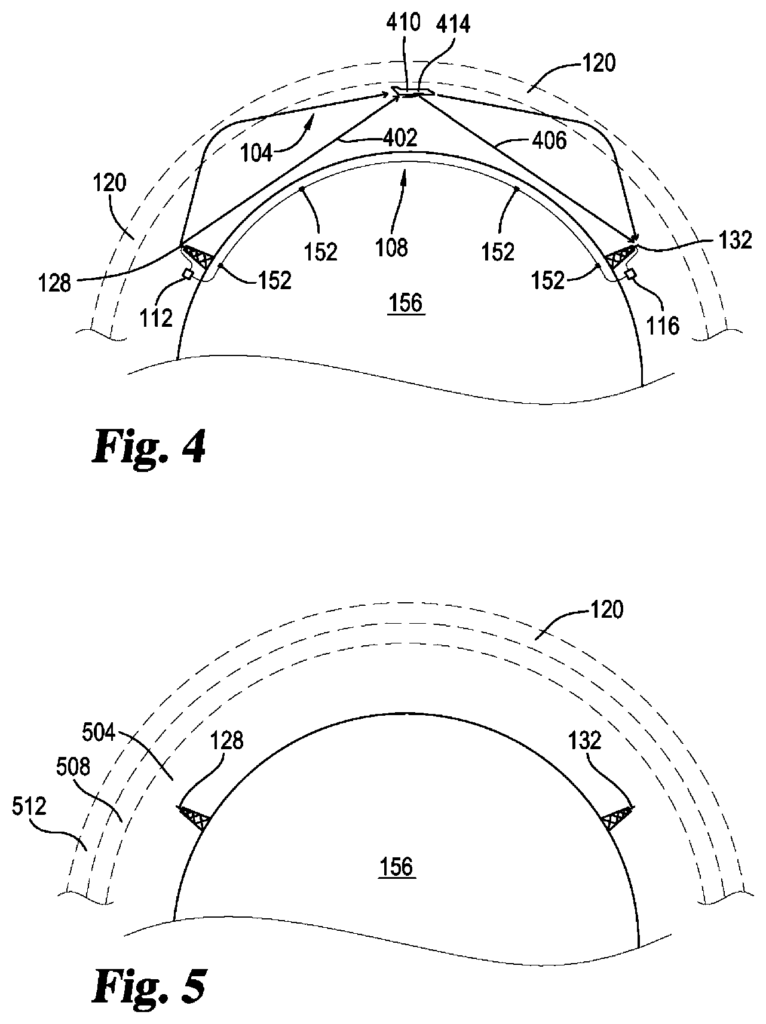
FIG. FIG. One or more repeaters are airborne along the first communication link, for example, in an aircraft or dirigible or balloon or any other device 410 that is designed to keep the repeater in the atmosphere. In this example signals sent from the first communications node 112. via antenna 128, may be received either by an airborne relay 414 as line-of-sight communication 402, as well as by skywave transmission as described elsewhere. The signals can be received by an airborne repeater and retransmitted either as line-of-sight communication 406 or via skywave propagation along the low latency links 104 to the second communication node 116.
Figures 5-7 illustrate additional details about skywave propagation. 5-7 . FIG. 5 illustrates the relationship between the system revealed and the various layers of upper atmosphere. 5 . “For radio transmission purposes, the upper atmosphere can be divided into successively higher layers as shown in the diagram: the troposphere 504, stratosphere 508 and the ionosphere 51.
The ionosphere has a high concentration ionized particle. The density of these ions is low in the farthest reaches of the ionosphere, but increases as the ionosphere gets closer to the earth. The sun’s powerful electromagnetic radiation, including high-energy UV radiation, energizes the upper region of the atmosphere. The solar radiation causes the air to be ionized into electrons, negative ions and positive ions. The radiation particles from outer space have such a high energy, that even though the density is low in the upper ionosphere, they are able to cause extensive ionization. As air density increases, the intensity of the ionization decreases. The highest degree of ionization occurs at the uppermost extremities of ionosphere while the lowest is found in the lower ionosphere.
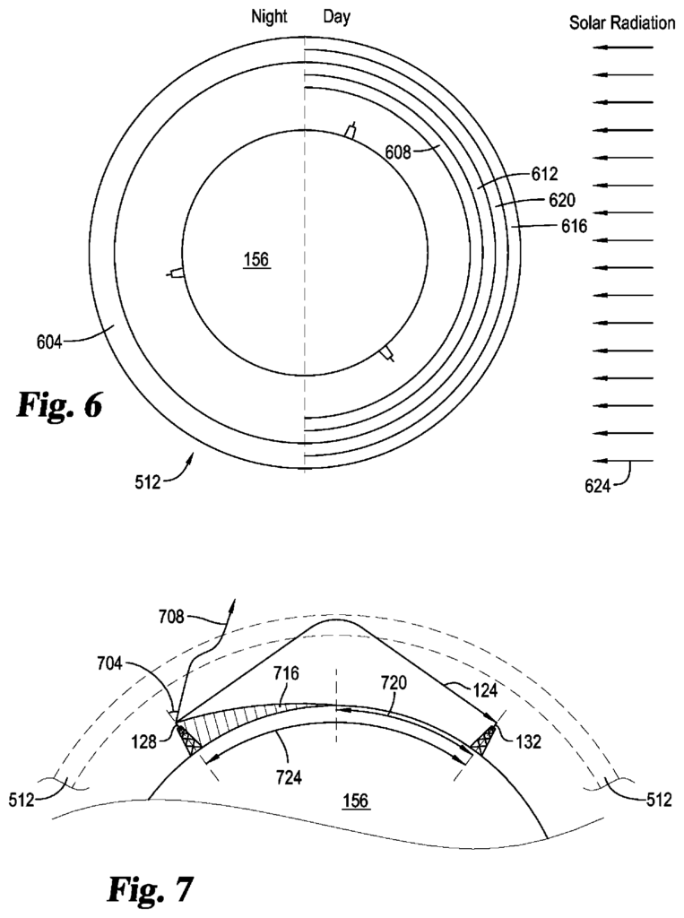
FIG. 512 illustrates the differences between ionization at the upper and lower extremities 512 of the ionosphere. 6 . FIG. 6 illustrates the ionosphere. Six has three layers, numbered D layer 608, F layer 604, and E layer 612. These are arranged from the lowest to the highest layer. F layer 604 can be divided into F1 (the upper layer) and F2(the lower layer), respectively, at 616. Layers 616 and 620 are present or absent in the ionosphere, and their height over the Earth varies with the sun’s position. The radiation of the sun 624 entering the ionosphere peaks at high noon. It then decreases at sunset, and finally reaches its lowest point at night. After the radiation is removed, the D and E layers 608 and 612 disappear. The F1 and F2 layer 616,620 also recombine during the night to form a single F 604 layer. The sun’s position varies in relation to any given point on Earth, so it is difficult to predict the characteristics of the ionosphere layers 608, 612 and 616. However, they can be determined through experimentation.
The ability of a radiowave to reach a distant location by using skywave propagation is dependent on several factors, including the ion density of layers 608-620 when they are present, the frequency of electromagnetic energy transmitted and the angle at which it was transmitted. If the frequency of the radio wave is increased gradually, the wave will reach a point where it cannot be refracted in the D layer 608, which is the lowest ionized layer within the ionosphere. The wave can continue to travel through the D layer 608 and on into the E Layer 612, where it may be too high in frequency to refractive the singles that pass through. Waves 124 can continue on to the F2 and F1 layers 620, possibly even 616 before being bent towards earth. The frequency of some waves may be higher than a critical frequency, making it impossible to refract the electromagnetic energy out of earth’s atmosphere (708).
So, above a certain wavelength, electromagnetic energy transmitted horizontally is carried into space without being refracted by the ionosphere. If the propagation angle 704 is reduced from vertical, certain waves may be refracted below the critical frequency. The angle of propagation can be lowered to allow electromagnetic waves 124 from antenna 128 to reach the Earth’s surface in a skip zone. This allows a skip distance to be traversed 724. The ability to successfully propagate skywaves over a skip distance 724 depends on both the transmission angle and the frequency. Therefore, the maximum frequency that can be used varies depending on the ionosphere condition, the desired skip distance 704, the propagation angle 704, etc. FIG. FIG. 7 shows that groundwaves and/or line-of-sight signals 716, which are not skywaves, will also be unlikely to cross the skip distance 724.
FIG. “FIG. 8 shows an example of an additional aspect of a communication device 800, which is similar to communication devices 112 and116. The communication node can have a processor 804. This processor is used to control various aspects of the communication node. The processor can be connected to a memory (816) that stores rules or commands 820. Also included may be devices for receiving user input and delivering output (I/O). These devices can include a keyboard, keypad, mouse, display, such as a flat-panel monitor, and similar, printers, plotters, 3D printers, cameras, or microphones. You can include any suitable device for user I/O. Node 800 can also have a network interface (832) that is responsive to processor 804 coupled with a communication network. Security module 828 can be used as well to reduce or eliminate third parties’ ability to intercept, jam or change data that passes between communication nodes 800. In one example, the communication node is implemented by a computer that executes software to control the interactions of the different aspects of node 800-.

Network Interface 836″ may be configured to transmit and receive data, such as command data (820) or triggering data that may be sent from a trigger system 840. Communication network 836 can be configured to send and/or receive data using skywave propagation without being coupled to any network, such as the Internet. Communication network 836, for example, may transmit and receive information over optical fibers (or other transmission lines) running along the Earth similar to transmission line 144 shown in previous figures.