Invented by Matthew Flego, Yehuda Ivri, Erik Cooper, Aaron Wisniewski, Samuel Wisniewski, Ovr Tech LLC
The Ovr Tech LLC invention works as follows
An air atomizer for dispensing fluids is provided.” In some implementations, the device can be used to generate atomized liquid, specifically but not exclusively for producing small droplets of scented oils and other fluids-based fragrances. In some embodiments the device is a tube shaped element with a proximal and distal opening. Media positioned within the tube are forced out through the proximal aperture via an aperture plate.
Background for Device to atomize fluid
There are many ways to produce fragrances. They can be used in different environments and systems. Some systems are passive such as air fresheners that use degradable media. Others have active devices to control the release into the air of the scented media.
In some embodiments, a device is provided that atomizes liquids and disperses them into the air. In certain implementations, there is a device for producing atomized liquid, specifically but not exclusively for the production of small drops of scented oils and other fluid based fragrances. In some embodiments the device consists of a tube with a proximal and distal opening. Media inside the tube can be forced out through the proximal aperture via an aperture plate. The aerosol-generating apparatus may have a tube. However, the device can also include other structures capable of vibrating to produce an aerosol.
In some embodiments, an aerosol-generating device (e.g. a tube) may also include at least one plate attached to the tube’s face. The device also includes an apertureplate that is attached to a proximal portion of the tubing, while the distal portion of the tube is connected with a fluid source to supply fluid to the aperture plate at the tube’s proximal part. The aperture plate may include a plurality apertures extending through the thickness of plate in some embodiments.
In some embodiments, a tube with a proximal and distal opening is used, in which fluid enters through the distal end, and then is forced to exit the proximal via an aperture plate. Fluid may already be present in the tube or added to it via the distal opening. This could happen by adding fluid while the device is operating and forcing the fluid out. In some embodiments the device comes with fluid already located in the tube.
The device also includes a circuit that can generate an electrical signal with a specific frequency and voltage. The frequency generator can be connected to the piezoplate and the piezoplate will generate cyclical stress wave which propagates down the tube. This produces oscillations which cause the aperture plate to vibrate and create a flow of liquid atomized through the apertures. In certain embodiments, at least one tube surface should have sufficient surface area to allow the attachment of the piezo substratum. In some embodiments the tube can be rectangular and the surface of the substrate can be attached to a large portion of the surface of the tube. In some embodiments the piezo is located closer to the distal end allowing stress waves to travel to the proximal aperture.
In some embodiments, an individual piezo is attached to the tube and generates longitudinal oscillations within the tube. In some embodiments the tube doesn’t bend because the tube shape has a high bending rigidity due to a high moment of inertia. The tube vibrates as the piezo can vibrate at a frequency that is resonant to the tube. This causes the stress waves that force the liquid out of the apertures.
In some embodiments, multiple devices can be arranged in a line. It may be desirable to have one side of the tube narrow so that multiple devices can be stacked with minimal space.
In some embodiments the induced frequency generated by the piezo is equal to that of the rectangular tube when it is bent or in a long-term mode.
In some embodiments the tube can be a rectangular tube with two faces that are sufficiently large to allow at least one element piezoelectric capable of generating an amplitude sufficient to be attached.
In some embodiments, a tube with a trapezoidal section and at least one surface that can be used to attach a piezoelectric component capable of producing amplitude is described.

In some embodiments, a tube with a circular cross sectional shape is equipped with a piezoelectric component disposed around the circumference of the tubing.
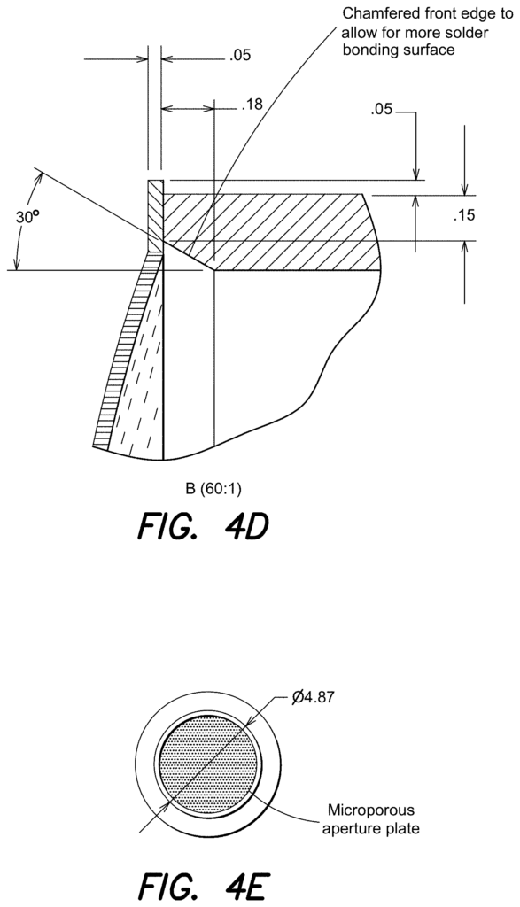
In one embodiment, the tube has a circular cross-section and one face is large enough to attach a piezoelectric component that can generate large amplitude. The tube’s width is between 0.05mm and 28mm, and its length between 1mm and 154mm in one embodiment. In some embodiments the device can be small enough to allow multiple elements to be arranged in an array that can be used in XR devices (e.g. augmented reality, virtual reality, mixed reality). In certain embodiments, a small device is preferred for some applications. However, the size can be optimized to avoid requiring an excessively high resonant frequencies. In some embodiments the aperture plate covers the entire end of tube and is attached to it via glue or solder. In some techniques the aperture plate may be circular and bent prior to connecting the edge of the tube. The aperture plates can also be flat or shaped like a dome, with the dome facing outwards from the end tube.
In some applications, the aperture is designed to perfectly fit the tube’s end. In some cases, the aperture size may be smaller than 10 m. Some applications may require apertures in the 5 m range (+/?2?m. In general, smaller apertures are preferred. However, the size of the aperture can be adjusted to reduce clogging or the force required to produce atomized liquid.
In some embodiments, tubes of different shapes and sizes can be operated at an optimal resonance frequency (e.g. by applying electrical signals). This frequency can be determined by the tube, piezoelectric plate and atomizer used. In some embodiments a range or optimal frequencies can be used and the optimal size of the piezoelectric elements may be selected for a specific resonant. In some embodiments the piezoelectric elements resonant frequencies are the same as the aperture plates. In some embodiments the size of the piezoelectric, tube, and aperture plate are optimized to produce aerosols.
Below, we discuss in more detail “Still Other Aspects, Examples, and Advantages of These Exemplary Aspects and Examples.” It is also to be understood that the above information and the detailed description of various aspects are only illustrative and intended to give an overview of the nature and characteristics of the claimed examples and aspects. All examples disclosed herein can be combined in any way consistent with one or more of the objects and aims disclosed herein. References to “an example” and “some examples” are also acceptable. ?some examples,? ?an alternate example,? ?various examples,? ?one example,? At least one example? This and other examples are not mutually exclusive. Or the like do not have to be mutually exclusive. They are meant to indicate that at least one of the features, structures, or characteristics described in the example can be found in another example. These terms are not all necessarily referring to one example.
BRIEF DESCRIPTION DES DRAWINGS
The accompanying figures are not meant to be drawn at scale. Figures are used to illustrate and provide a deeper understanding of various aspects and examples. They are also incorporated into and form a part this specification. However, they are not meant to define the limits of any particular example. Together with the rest of the specification, the drawings serve to explain the principles and operations of described and claimed examples and aspects. Each identical or nearly identical part that is shown in different figures is denoted by the same number. To ensure clarity, some components may not be labeled on every figure. “In the figures:
FIGS. “FIGS.
FIGS. “FIGS.
FIGS. “FIGS. 3A-3F illustrate various views and embodiments of an assembly with multiple cylindrical tubes.

FIGS. “FIGS.