Invented by Chang Woo Ha, Sang Cheol Shin, Byoung Own Min, Samsung Electronics Co Ltd
The Samsung Electronics Co Ltd invention works as follows
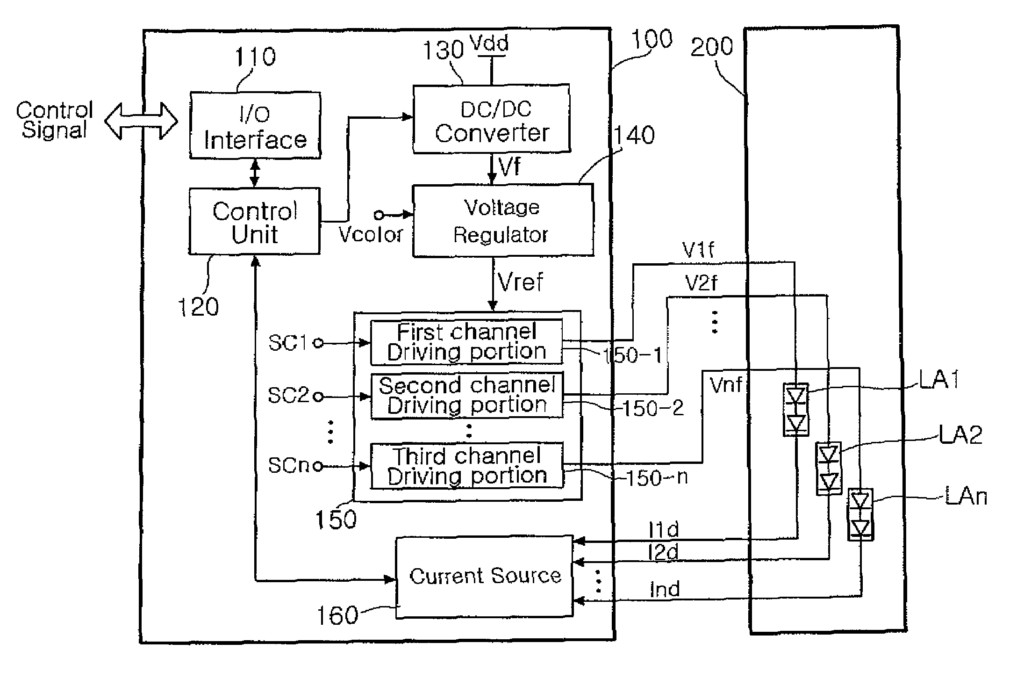
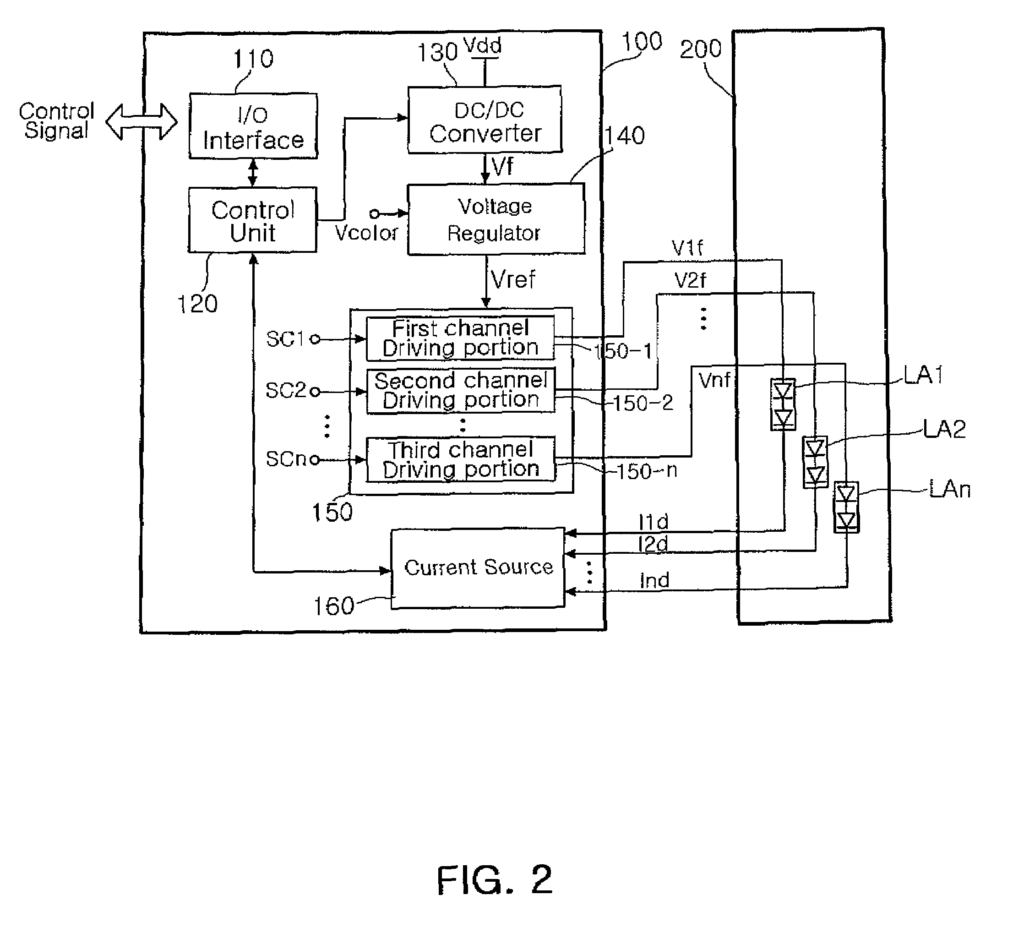
The drive unit of a color LED backlight that includes a number of color arrays includes: an I/O for input/output of signals; a control module for controlling the driving voltage and current according to the brightness control signal output by the I/O unit; a DC/DC Converter for converting an operating voltage into the drive voltage in accordance with the driving-voltage control of this control unit; a voltage regulator to regulate the driving-voltage output of the DC/DC regulator to a reference without ripple

Background for Driver device with color LED backlight
1. “1.
The present invention is a drive system for a color light-emitting diode used in a display device, and, more specifically, a device for a backlight color LED that can precisely adjust the forward voltages on color LED arrays per channel, thereby providing optimal forward voltages for the respective color arrays. It also has the ability to independently set the number of LEDs within each color array and reduce ripples of the forward voltages through voltage regulation.
2. “2.
In general, there are at least 288 million display products demanded annually in the mobile display market. This includes mobile phones, MP3 Players, Personal Media Players (PMP), Automotive Navigators, Mobile or Vehicle DVD/AV Systems, and Laptop Computers. The majority of the mobile display is occupied with thin film transistor-liquid-crystal display (TFTLCD) technologies. The competition between enterprises to improve the price and performance of TFT-LCDs is getting fierce.
Since TFT does not emit light by itself, the TFT LCD needs an additional light-emitting element like a backlight (BLU). BLUs can take on different forms. Commercially available LCD-BLUs use cold cathode fluorescence lamps (CCFL). The CCFL is a good choice for its high brightness, low cost of manufacture, simple driving circuit, and thin tube shape. “However, because the CCFL has a low resistance to external impacts, a TFT-LCD mobile with a size less than 5 inches uses a white led.
FIG. “FIG.
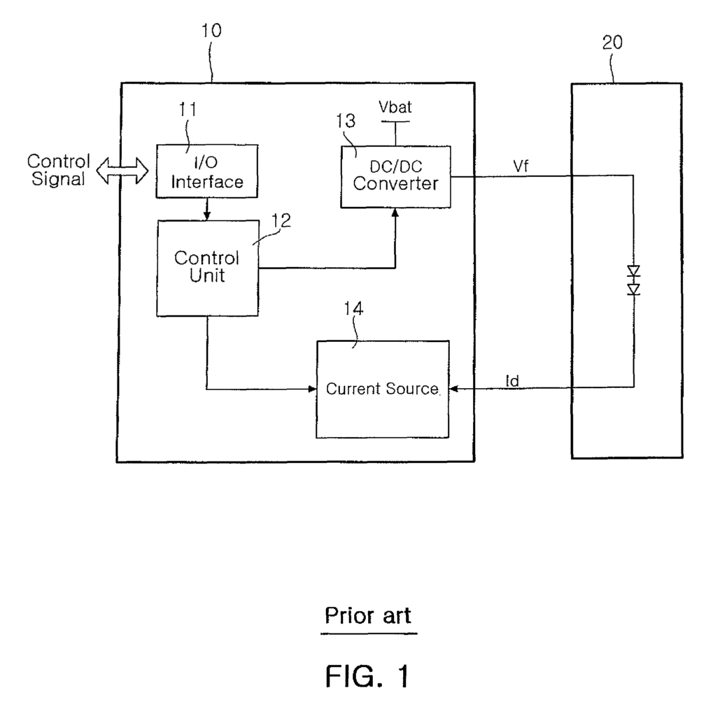
The conventional drive 10 of the white backlight LED shown in FIG. The white LED light 20 is driven by 1. It includes an I/O Interface 11 for input/output of a signal. A control unit 12 controls a driving voltage according to the brightness control signal that comes from the interface 11.
Each white LED backlight consumes a driving current of approximately 10 mA, and a voltage of 1.8 to 3.0 V.
The conventional drive device for the white backlight LED adjusts the amount of driving current of the LED by using a method to control the amount of current of the LED. The control unit 12 can send a signal to the current source 14, allowing it to adjust brightness when in burst mode.
However in the conventional drive system of the white LED rearlight, ripples are generated in the output voltage of a DC/DC converter. So, ripples are generated in the forward voltage. A boost-up voltage for the DC/DC Converter cannot be changed easily.

The forward voltage of each color led cannot be adjusted precisely.
It is not possible to achieve accurate color reproduction with a CCFL, or a white LED. The color reproducibility of these devices falls between 70 and 80% below the NTSC standards. To solve this problem, active research is being conducted to implement color reproducibility at least 90 percent using a colored light source. Color LEDs (RGBLEDs) have begun to be commercialized on the LCD-HDTV market, and expert LCD monitor markets. An application of these LEDs is being gradually expanded with the development of technology and increase in production.
However in the conventional drive of the white LED rearlight, color LEDs are different due to LED characteristics. This is the level of forward voltage Vf and optical output efficiency. A function to adjust the forward voltage Vf was therefore required. “When the LEDs in series are connected, the number or difference between forward voltages Vf can increase.
In addition, in mobile devices, the DC/DC converter boost-up is used to generate the forward voltage required for driving the LED. The ripple generated by the DC/DC boost-up converter causes the voltage to be unstable.
The present invention was made to solve the problems mentioned above. Its object is to provide a color backlight drive device that can precisely adjust the forward voltages in each channel, to provide the optimal forward voltages for the respective color arrays. This is done by independently setting the number LEDs per color LED matrix, and reducing the ripple of forward voltages through voltage regulation.
The following is a description of a drive unit that can be used to drive a color backlight with a number of color LEDs. It includes: an input/output interface, a DC/DC Converter for converting a power supply voltage to the required driving voltage, according to driving voltage control from the control unit, a voltage controller for regulating driving voltage outputs from the DC/DC Converter to a constant reference voltage, a multi-channel unit to convert the reference voltage from the voltage converter into the forward voltages
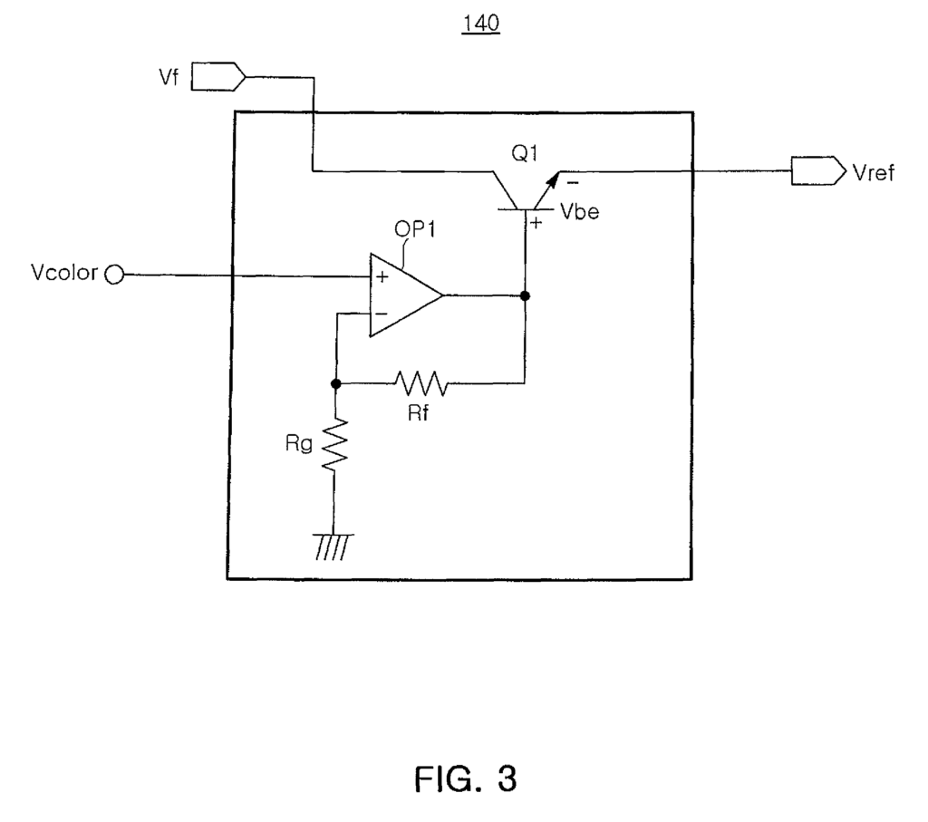
The voltage regulator may comprise an operational amplifier for non-inversion-amplifying a color voltage; and a transistor for converting the driving voltage output from the DC/DC converter into the reference voltage according to the level of an output voltage of the operational amplifier.
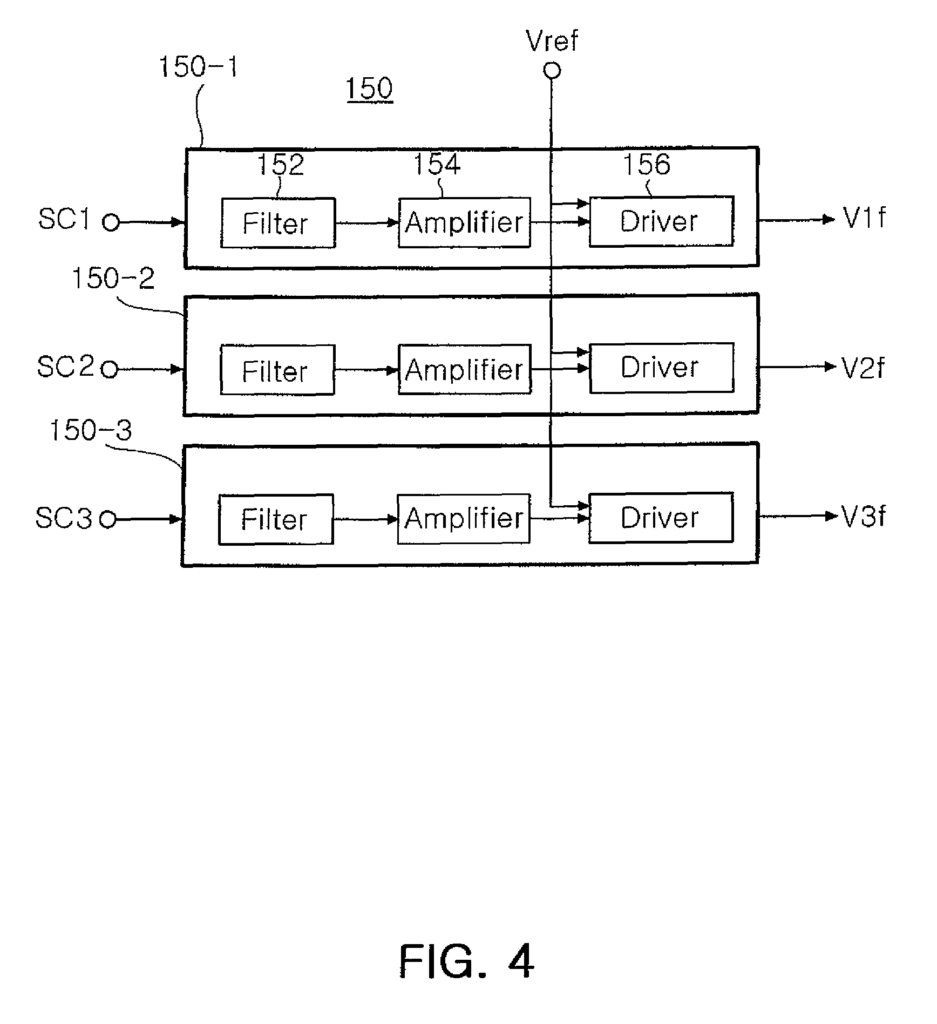
The plurality control signals can include first, third and second control signals. The plurality color LEDs arrays can include first, third and second color led arrays. And the multi-channel unit may include a first channel portion for changing the reference output voltage from the regulator into the first forward voltage for the first color array in accordance with the first control. A second channel portion for changing the reference output voltage from the regulator into the second forward voltage for the second color array in accordance with the second control.
The first channel-driving portion can be implemented with a red driving portion. The second driving portion is implemented with a green driving portion. And the third driving portion is implemented with a blue driving portion.
The first, third and second channel driving portions can each be comprised of a filter that filters a respective one of the second, third and first control signals in a band predetermined; an amplifying amplifier to amplify the control signal from the filter at a gain predetermined; and a converter for converting reference voltage from the voltage regulator output into forward voltage according the the control signal from the amplifier.

The first, third and second control signals can be digital signals. Each of the first channel driving units could include a digital/analog convertor (DAC) that converts a corresponding digital signal into an analog signal.