Invented by Thomas David Novlan, Milap Majmundar, Arunabha Ghosh, AT&T Intellectual Property I LP
The AT&T Intellectual Property I LP invention works as follows
The establishment of integrated links, which include integrated wireless backhaul communication links and access communications channels, is made easier by using multiplexed synchronization signals to enable synchronization among the relay transmission points devices and a random channel access procedure to complete it. It is possible to maintain the integrated wireless backhaul communication links and access communications by using a measurement signal.
![]()

Background for Initial Access and Radio Resource Management for Integrated Access and Backhaul (IAB), Wireless Networks
Radio technologies have evolved rapidly in cellular communication since the launch analog cellular systems back in 1980. Starting with the first generation (1G), second generation (2G), third generation (3G), in the 2000s and the fourth generation (4G), in 2010s. This includes variants of LTE such as Time Division LTE (TDLTE), Frequency Division Duplex LTE, Advanced Extended Global Platform (AXGP), LTE Advanced (LTE A), and TDLTE Advance (TDLTE A) and other releases. Cellular networks have seen a tremendous increase in traffic, and this growth is not expected to slow down. This growth is expected to include not only humans but an increasing number of machines communicating with each other. For example, surveillance cameras and smart electrical grids. Sensors, home appliances, other technologies and connected homes. Intelligent transportation systems, such as the Internet of Things. Other technological advancements include 4K video, augmented realities, cloud computing and industrial automation.
The need for ultra-low latency, increased throughput, and massive connectivity are driving the development of future networks. The fifth generation (5G), also known as New Radio (NR), access networks are being developed. They are expected to be able to handle many different use cases, including mobile broadband (MBB) or machine type communication (e.g. involving IoT). Mobile broadband 5G wireless networks will be able to handle the exponentially growing data traffic, allowing people and machines to experience gigabit data speeds with almost zero latency. In comparison to the fourth-generation (4G) technologies such as Long-Term Evolution (LTE) and Advanced LTE networks, which target much higher throughput and low latency, 5G offers better speeds and coverage. It also uses higher carrier frequencies, e.g. higher than 6 gigahertz, and wider bandwidths. A 5G network can also increase network expansion to hundreds of thousands connections.
The present patent application describes systems and methods to integrate wireless backhaul communication between relay transmission points (rTPs) with the access communication between user equipment and rTPs in 5G networks and other next-generation networks.
The above background on wireless networks was not meant to be exhaustive. It is only intended to give a context overview of current issues. The following detailed description may reveal additional contextual information.
The subject disclosure will now be described in reference to the drawings. Throughout, like reference numbers are used to identify similar elements. The description below and the drawings annexed illustrate certain aspects of the subject. These aspects, however, are only a small part of the many ways that the principles of this subject matter can actually be used. The following detailed description, when viewed in conjunction with the provided illustrations, will reveal other aspects, advantages and novel features. To provide a better understanding of the disclosed subject matter, numerous details will be provided in the following description. However, it may be obvious that the subject disclosure could be performed without these specifics. Other times, well-known devices and structures are shown as block diagrams to make it easier to describe the subject disclosure.
The methods described herein (e.g. processes and logic flow) can be executed by devices” (e.g. a UE or a node in a network, etc.). The devices may include programmable processors which execute machine executable instruction to perform the operations described in this specification. As an example, devices that include circuitry and components can be described in FIG. “Examples of such devices can be devices comprising circuitry and components as described in FIG. 14.
The present application describes a system and method for integrating wireless backhaul communication between relay transmission point (rTP) devices and access communications between the user equipment (UE), and rTPs, including in 5G or other next-generation networks. In some embodiments, the rTPs multiplex access links and the backhaul links by using time division (TDM), or frequency division (FDM), hybrid (FDM/TDM) or space division (SDM). This can include the transmission of the signals/channels used as part of the initial access. The wireless backhaul communication link connections (referred herein as “backhaul links”) can be established by initial discovery of the rTPs. Initial access is then performed by the rTPs. The rTPs may be located one hop or more away from the network node. 5 below). The rTPs will then continue monitoring the sync signal for the maintenance of the links. Radio resource management (RRM), or radio resource allocation, measurements are made periodically (e.g. reference signal received power, beam-specific measurements, etc.). The backhaul link signals facilitate communication on the links. Functionality can also comprise radio resource control (RRC) connection establishment and configuration/reconfiguration.
The operability of using transmission schemes (e.g., multiplexing of access/backhaul traffic in time/frequency/space) to increase utilization of backhaul links can allow for ultra-dense deployment of mmWave transmission points (TPs) without having to increase the number of wired transport nodes and connections proportionately, which can allow for increased efficiency and scalability. Due to phased array transmissions (unlike cellular bands which require separate radios), access and backhaul can be used on the same radio. As such, duplex operation is not required. The system and method can also allow for route switching that is faster than RRC timescales, which can reduce blocking of mmWave communications. The present systems can also be used for route optimization and multi-hop scheduling. They can also be used to re-use physical channels, higher layer procedures, and access physical channels, which can lead to greater efficiency.
This section describes different aspects of example operating environment, such as wireless communication systems and methods according to the present application. It includes a typical wireless communications system and a wireless network communication system that comprises relay node devices. Also, it describes different transmission schemes which can be used for integrating access and backhaul between UEs, and rTPs, (which can either be RNs or nodes of network). This section also describes layer 2 versus 3 relay switching and multi-hop-backhauling, as well as multi-site connectivity.
FIG. “FIG. In some embodiments, the system 100 is a wireless network that’s serviced by several wireless network providers. In some embodiments, the system 100 may include one or more user devices (UEs), such as 102 1, 102 2. . . The UE 102 can be any user equipment device, such as a mobile phone, a smartphone or cellular-enabled laptop (e.g., containing a broadband adapter), if it has vertical and horizontal antenna elements. A UE 102 is any user equipment, including a mobile, a smartphone or cellular-enabled laptop (e.g. with a broadband adapter), a computer tablet, a wearable, a VR device, a heads up display (HUD) gadget, a smart-car, a device for machine-type communications (MTC), etc. UE 102 may also include IoT devices capable of wireless communication. UE 102 may be a mobile system (MS) for global system of mobile communications (GSM). The network node (e.g. device network node) facilitates wireless communications between the UE, and wireless communication networks (e.g. the one or multiple communication service provider networks 106 described below). The UE 102 is able to send and/or get communication data wirelessly via the network node 104. “The dashed arrows from the network node 104 towards the UE 102 represents downlink (DL), and the solid arrows from the UE 102 toward the network nodes 104 represents uplink (UL).

The term “network node” (e.g. network node device) is used to describe any network node that serves a UE 102, and/or connects to other network elements or network nodes from which the UE 102 may receive a radio transmission. In typical cellular radio networks (e.g. universal mobile telecommunications systems (UMTS)), a node network can be referred as base transceiver station (BTS), base stations (BS), radio network nodes (radio network nodes), NodeB, eNodeB(e.g. evolved NodeB), and so on. In 5G, the device can be called a gNodeB, such as gNB. The network node can include multiple antennas to perform various transmission operations, such as MIMO. A network node may consist of a cabinet or other enclosures for protection, an antenna mast and antennas. Depending on the antenna type and configuration, network nodes can be used to serve multiple cells. Network nodes (e.g. network node 104) include, but are not restricted to, NodeB devices (base station), access point (AP) and radio access networks (RAN) devices. The network node 104 may also include radio node devices that support multi-standard radio, including: an MSR BS (base station), an eNode B (eNode B), a network controller, a Radio Network Controller (RNC), a Base Station Controller (BSC), a relay, a Donor Node Controlling Relay, a Base Transceiver Station (BTS), a Transmission Point, a Transmission Node, a Remote Radio Unit (RRU),
The system 100 can also include one or multiple communication service provider network 106, which facilitates the provision of wireless communication services via network node 104, and/or other network devices (not depicted) that are part of the one or several communication service provider network 106. One or more communication provider networks 106 may include a variety of networks including cellular networks (including femto and picocell), microcell networks (including microcells), internet protocol networks (IP), Wi-Fi service networks Broadband service networks Enterprise networks Cloud based networks etc. In at least one implementation of system 100, the wireless communication network can span multiple geographic areas. In this implementation, one or more communication provider networks 106 may be or comprise a wireless communication system and/or additional devices and components (e.g. additional network devices and cells, additional UEs and network server devices). One or more communications links can connect the network node 104 to one or multiple communication service provider networks. One or more communication links 108 may include wired components such as a T1/E1 telephone line, digital subscriber lines (DSL), asymmetric DSLs (ADSL), optical fiber backbones, coaxial cables, etc. Wireless link components can be included in the one or more communication links 108, such as line-of-sight links or non-LOS, including terrestrial air interfaces or deep-space links (e.g. satellite communication links for navigation).
Wireless communication system 100 may employ different cellular technologies, modulation schemes and other techniques to enable wireless radio communications (e.g. between the UE 102 & the network node 104). For example, system 100 can operate in accordance with a UMTS, long term evolution (LTE), high speed packet access (HSPA), code division multiple access (CDMA), time division multiple access (TDMA), frequency division multiple access (FDMA), multi-carrier code division multiple access (MC-CDMA), single-carrier code division multiple access (SC-CDMA), single-carrier FDMA (SC-FDMA), orthogonal frequency division multiplexing (OFDM), discrete Fourier transform spread OFDM (DFT-spread OFDM) single carrier FDMA (SC-FDMA), filter bank based multi-carrier (FBMC), zero tail DFT-spread-OFDM (ZT DFT-s-OFDM), generalized frequency division multiplexing (GFDM), fixed mobile convergence (FMC), universal fixed mobile convergence (UFMC), unique word OFDM (UW-OFDM), unique word DFT-spread OFDM (UW DFT-Spread-OFDM), cyclic prefix OFDM CP-OFDM, and resource-block-filtered OFDM. It is described that the system 100 has various features and functions, such as the UEs 102, network device 104, and other devices, which are configured to transmit wireless signals by using one or multiple multi-carrier modulation scheme.
System 100 can be configured in various ways to offer and use 5G wireless networking functionalities and features. The 5G wireless networks will be able to meet the exponentially growing data traffic, and allow both people and machines to experience gigabit data speeds with almost zero latency. 5G is more flexible than 4G in terms of traffic scenarios. In addition to data communication between conventional devices (e.g. phones, smartphones and tablets, PCs and televisions with Internet access, etc.), 5G networks can also support a variety of traffic scenarios. In addition to the data communication supported by 4G, 5G can also be used to support machine type communications, such as those between smart cars and driverless car environments. The ability to dynamically adjust waveform parameters according to traffic scenarios (e.g. OFDM and other schemes) while maintaining the benefits of multi carrier modulation schemes can make a significant contribution towards the high speed/capacity requirements of 5G networks. Waveforms that divide the bandwidth into sub-bands can accommodate different types of services in different subbands using the most appropriate waveform and numbering, leading to improved spectrum utilization for the 5G networks.
The 5G network can support data rates of several tens of megabits per second for tens of thousands of users, 1 gigabit per second to be offered simultaneously to dozens of workers on the same office floor, etc. The 5G network can support data rates up to several tens megabits per seconds for thousands of users. It could also offer 1 gigabit of bandwidth to workers in the same office.
The 5G network will be able to use higher frequencies (e.g. >6GHz) in order to increase capacity. The millimeter-wave spectrum (between 30 GHz to 300 GHz) is currently underutilized. “Millimeter waves are shorter wavelengths, ranging from 10 millimeters up to 1 millimeter. These mmWave signal suffers severe path loss and penetration loss.
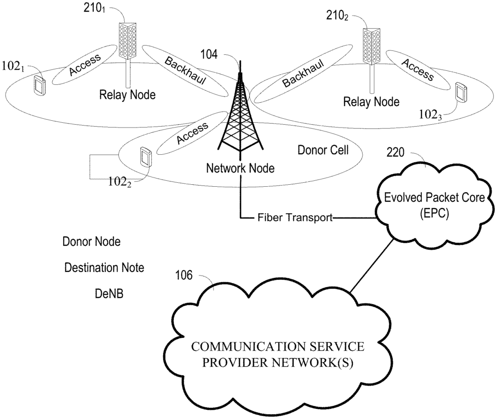
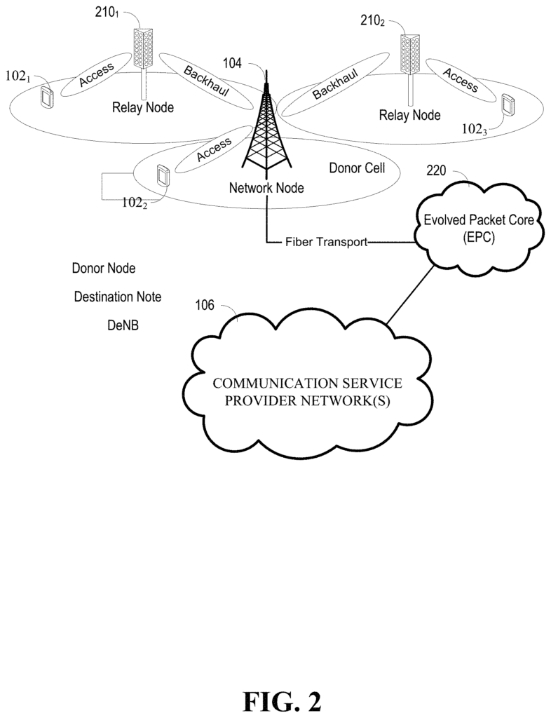
FIG. “FIG. Two example RNs are shown in FIG. RNs are typically located on the outer edge of the network node’s 104 cell. They can help meet the increasing demand for coverage and capability. An RN can be smaller than a node and consume less power. It can connect to a node via a backhaul, which can then also be called a donor or destination node. RNs are able to increase the data rate in the network. They can also control their own cell (e.g. have their own cell ID) and be able to perform RRM. Mobility management (e.g. handovers) is possible. For example, a UE, such as UE 102 1, can send a signal over a wireless communication link (e.g. access link) to RN 210 1 which can relay the signal back to network node 104. Typically, a UE is connected to the network node 104 or an RN 210 but not both. In FIG. In FIG.
The network node 104 in FIG. The network node 104 of FIG. The network node can be configured to communicate with an evolved packet core 220, for instance, via fiber transport. The EPC is used as an interface to connect to networks like the internet, corporate networks, IP multi-media subsystems etc. (e.g. one or more networks of communication service providers 106).
The network points (e.g. network node 104) can be referred as relay transmission point (rTP). In example embodiments of this application, backhaul communications can be combined with access communications between user devices (UEs) and rTPs. These communications, for example, can be multiplexed by the scheduler in an rTP. The scheduler is then able to determine the resource allocations for transmissions from UEs to rTPs and between rTPs. Schedulers typically assign resources according to a variety of criteria (e.g. base station throughput, latency for users, fairness etc.). The conditions and factors (e.g. the condition of the channels and number of rTPs in a cell) will determine how resources are allocated. The schedulers for the rTPs are able to select multiplexing schemes to integrate transmissions from the access links and backhaul links. Referring to FIG. The network node 104 may be receiving and sending signals both from RN 210 1 and UE 102 2. Transmissions can be multiplexed to prevent interference.
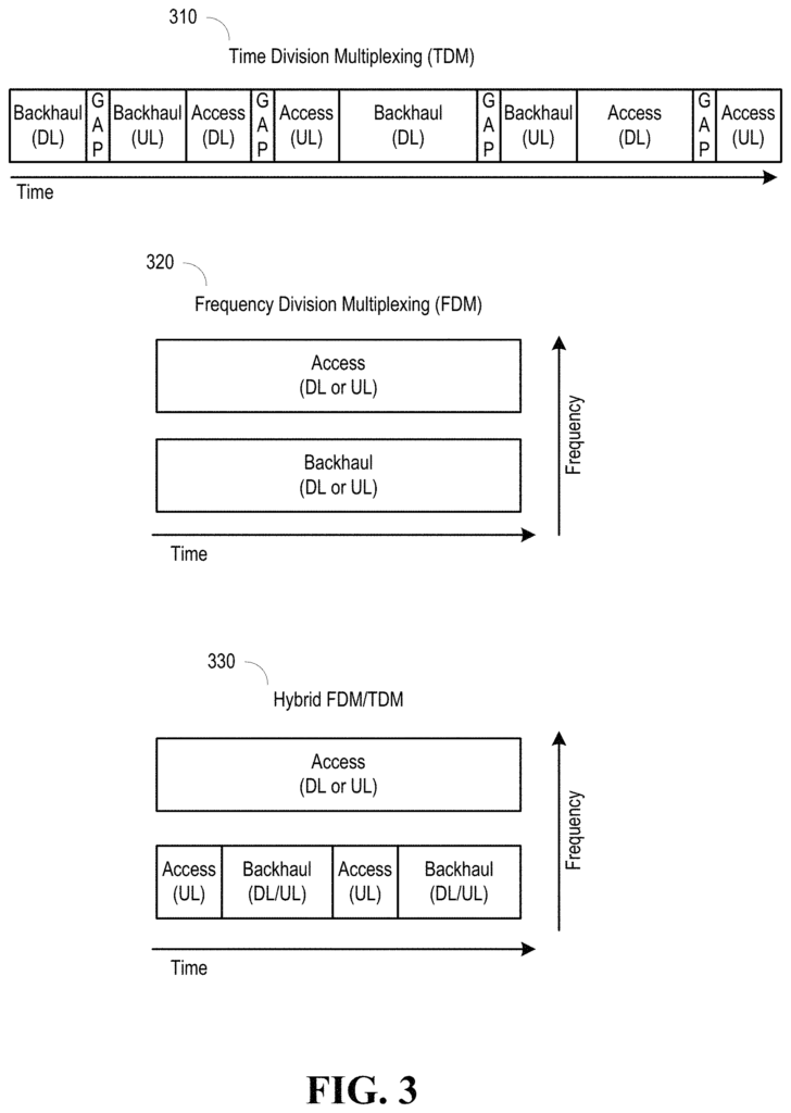
Here are some examples of transmission schemes that integrate access and backhaul. FIG. FIG. 3 illustrates transmissions using time division multiplexing 310, frequency-division multiplexing 320 and hybrid FDM/TDM for integrating backhaul transmissions (in band or out ofband). In the TDM example transaction, transmissions for access downlink, access uplink, and backhaul can be performed at different times. FDM schemes are also possible, whereby transmissions for the uplink, downlink, and access links are all made at one frequency and transmissions for the backhaul and access links are made at another frequency. Referring back to FIG. In the hybrid FDM/TDM example, in which access transmissions for uplinks and downlinks are sent on one frequency while access transmissions and backhaul transmissions, with time slots assigned, can be sent on another frequency. Although not shown in FIG. In addition to frequency and time, transmissions can be multiplexed spatially. “Beamforming and directional transmittals allow transmissions to be made at the same time and frequency, but in a different spatial direction or magnitude in order to reduce interference.

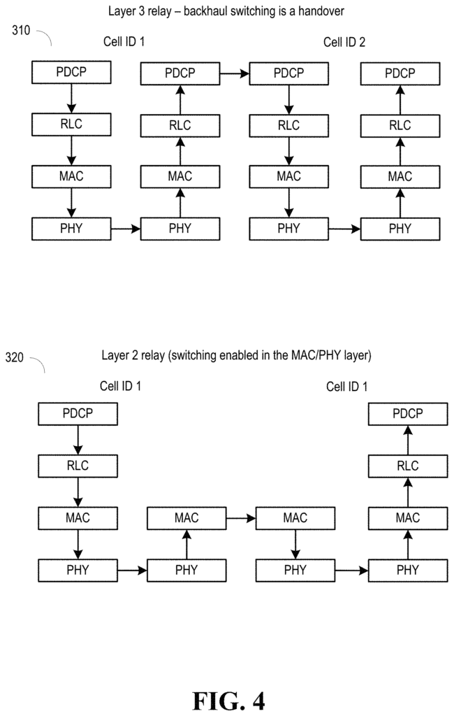
With respect to layer 2 vs. layer 3 relay switching, FIG. 4 illustrates user plane protocol stack diagrams showing some of the different protocol layers for a layer 3 relay and a layer 2 relay, which can be used to illustrate the difference between layer 3 and layer 2 relay switching. The physical layer (PHY) layer is responsible for coding/decoding, modulation/demodulation, multi-antenna processing, and mapping of signals to the appropriate physical time-frequency resources. Mapping of transport channels to physical channels is also handled at the PHY layer. The media access control MAC layer is responsible for multiplexing of radio link control (RLC) protocol data units, HARQ retransmission (e.g., error correction through HARQ), scheduling for uplink and downlink, logical channel prioritization. The RLC layer is in charge of segmentation, concatenation, ARQ retransmission (e.g., error correction through automatic repeat request (ARQ)) and in-sequence delivery to higher layers. The packet data convergence protocol (PDCP) layer is in charge of compression of the IP header of user packets (e.g., using the robust header compression (RoHC) protocol) to reduce the number of bits transmitting over the radio interface, PDCP is ciphering, integrity protection for the C-plane, in-sequence delivery and retransmission of PDCP service data units (SDUs), and duplicate detection.