Invented by David Dearman, Chun Yat Frank Li, Erica Morse, Google LLC
The Google LLC invention works as follows
The inventions include systems, devices, methods and computer program products for aligning virtual reality components. A method example includes detecting first inputs from a virtual-reality system handheld controller, informing a user of the direction to be oriented, and detecting second inputs from the handheld.

Background for Methods, apparatus and software to align components within virtual reality environments
A virtual-reality (VR) system creates an immersive virtual world for the user. The immersive environment, for example, can be in three dimensions (3D), and include virtual objects that the user can interact with. The immersive virtual environment can be experienced by the user through various display devices, such as a helmet, other head-mounted device with a display, goggles, glasses or any other device that allows the user to view a display.
The user can interact with a virtual environment by using physical movements and/or electronic devices to personalize the interaction. The VR system, for example, can include sensors that track head or body movements. The VR system may also include a handheld electronic device with sensors and other components. This handheld device can be used by the user to interact and navigate within the virtual environment.
Some aspects of the invention perform a method which includes detecting first inputs from a handheld control of a virtual-reality system, and instructing the user to align the handheld in a specified direction. Then, they detect a second inputs from the handheld, and store alignment data that represents an alignment of handheld.
The computer program product includes code that, upon execution by processing circuitry in a virtual-reality system configured to create a virtual-reality environment, causes that processing circuitry perform a method, which includes: detecting a 1st input from a hand controller of the Virtual Reality System, and, upon detecting that first input, communicatively connecting the hand controller to the head mounted display and instructing the user to align a handheld control in a specified direction. Detecting a 2nd input from the
The electronic apparatus can be configured to create a virtual environment. It includes memory and controlling circuitry that is coupled to the memory. The controlling circuitry is configured to detect a first output from a hand-held controller of the virtuality system.
Some aspects of the invention include a method which includes detecting input from a hand-held controller of a Virtual Reality System, communicatively connecting the handheld to a head mounted display of the Virtual Reality System in response the input, displaying a first icon associated with a handheld control, and second symbol associated to the head mounted display in response communicatively linking the handheld to the display, and then storing data that represents alignment of the hand-held controller with the head mounted display when the first and second symbols overlap at
The method includes instructing the user to rotate the head mounted display in the designated direction as the input is being detected. It also displays in the virtual reality scene a symbol representing the orientation.
According to one aspect, a computer-readable media has recorded and embodied instructions thereon that, when executed on a processor in a computer system cause the computer to perform any of these methods and processes described herein.
The drawings and description below provide details on one or more of the implementations. The description, drawings and claims will reveal other features.
Now, we will refer in detail to examples that are not limited by this disclosure. Examples of these examples can be seen in the accompanying illustrations. In the following examples, like reference numbers refer to similar elements. If like reference numbers are shown, the corresponding descriptions are not repeated. Instead, the reader is directed to the previous figure(s) that were discussed for a description.

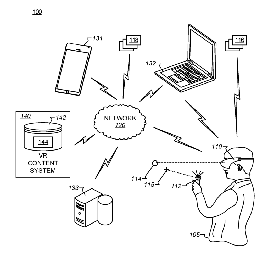
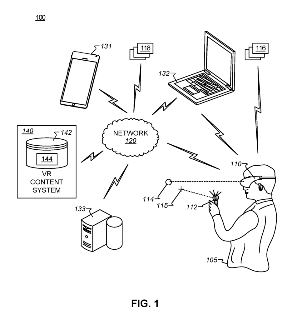
Turning to FIG. A block diagram of a virtual reality (VR), or example system, 100 is shown in Figure 1. The VR system 100 can be used to create and interact with a 3D VR environment. The system 100, in general, provides the 3D virtual reality environment and VR content to enable the user to view, interact, and/or use the examples described. The system 100 provides the user with options to access content, VR controls, applications, virtual objects and other VR controls by using eye gaze or movements in the VR environment. The VR example system 100 shown in FIG. The example VR system 100 of FIG. “Another user 105 is shown wearing the HMD and holding the handheld control 112.
The user 105 may align the HMD and controller 112 using the examples provided herein. The alignment can, for example, be performed as part of an initialization procedure or to correct drifting between the HMD and controller over time. The HMD 110 can be aligned to the controller 112. This will align the HMD 110’s representation of the controller in the VR environment with the actual position of the controller within the HMD 110. The alignment of either the HMD 110 or the controller 112 may drift in relation to a virtual scene. The embodiments disclosed herein may be used to realign the HMD 110 or the controller 112 with a VR scene.
In some embodiments, both the HMD 110 (head-mounted display) and the controller 112 (controller) can independently measure rotational and/or movement changes. The HMD 110, and the controller 112, independently track their respective orientations or poses using these measurements. In some embodiments the pose comprises a position as well as an orientation. Position can be represented as three degrees of flexibility (3DOF), such as forward/backward, right/left, and up/down. Orientation can also include three rotational elements, such a pitch (i.e. rotation around the Y-axis), roll (i.e. rotation about X-axis). In some embodiments, pose can be represented by six degrees (6DOF), which include forward/backwards (X coordinate), left/right (Y coordinate), down/up (Z coordinate), roll (i.e. rotation about X-axis), and pitch (i.e. rotation about Y-axis). Other embodiments are also possible, even though many examples are described herein in terms of aligning poses of the HMD 110 with the controller 112. Some embodiments, for example, align the HMD 110 or controller 112 in one direction or another. The technology described herein can be used to align the HMD 110 and/or controller 112 with each other or with a virtual scene.
Over time, as both the HMD 110 (head mounted display) and the controller (112), independently track their poses and numerical discrepancies accumulate, the HMD 110’s alignment and controller 112’s can drift. After some time, for example, the position of the HMD 110 relative to the controller 112 in real space could be different from the position of the virtual controller 112 in relation to the HMD 110 virtual representation in the VR environment.
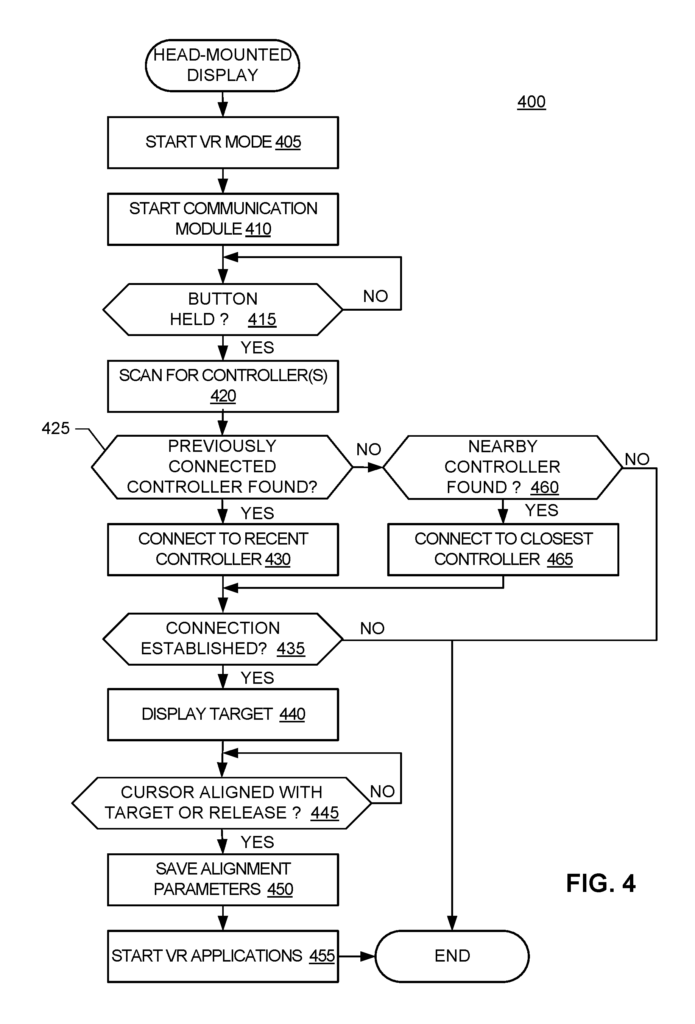
In one example, an alignment process can include detecting the pressing of a button on a first component, such as the handheld controller 112. The controller 112 is then communicatively coupled to a secondary component, such as the HMD 110 in response. A first symbol, for instance, associated with HMD 110 (e.g. a target 114), and a 2nd symbol, associated with controller 112, are displayed in a virtual reality scene in response. The cursor 115 may be represented by a laser or a ray that is associated (or emits from) the handheld control. The user is instructed by the HMD to point at the first symbol and/or to direct their eyes in that direction. They are also instructed to point the handheld controller 112. The controller 112 can also store data that represents the alignment of the HMD 110 to the controller 112. This data is stored when the cursor 115 and target 114 overlap in the VR scenes. In some examples the VR scene is changing while the target and cursor are being displayed.
In some examples, alignment data is used to correct at least one component in the pose of the HMD 110 and the controller 112. When a user tries to point the HMD 110 and controller 112 in the same direction (e.g. straight ahead, to the left, etc.), the alignment data may be used to correct the pose of the controller 112. The controller 112 can be pointed in a direction different from the HMD 110. Example alignment data is an offset that can be applied to a 3DoF model or 6DoF model of the controller 112. This reference model is maintained by either the HMD 110, or another component in the system 100. By adding alignment data values to 3DoF or 6-DoF coordinates, you can change a measured pose into a corrected one. Alignment data can, for example, represent the difference between a pose of an HMD compared to a controller. The alignment data can be used to align the HMD with an origin point or a designated alignment point in a VR scene. 9).
In some cases, the button might need to be held down. In some cases, the HMD 110 and controller 112 are inverted, for example, pressing a button on the HMD 110 instead of the controller 112. “Or, buttons must be held down on the HMD 110 and handheld controller 112.
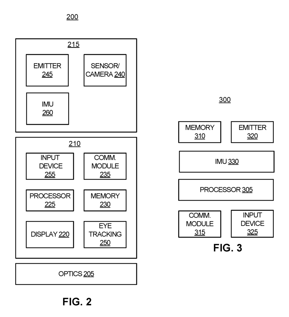
The HMD 110 can have a camera 240 (see FIG. The HMD 110 may include a camera (see FIG. The HMD 110 can include a camera 240 (see FIG. Sensors/cameras (see FIG. You can use any number, type, or combination of emitters, cameras, sensors, or images. Similarly, the pose of the handheld control 112 can be determined by using the sensor/camera and emitter 320. The handheld controller 112 can also be posed using the sensor/camera 118 and an emitter 320 (see FIG. The HMD 110, or any other device (e.g. devices 131 to 133, discussed below), of the VR system, can determine the pose. This may also be done by the computing devices P00 and/or P50 shown in FIG. 12.
As shown in FIG. The example VR system 100 can include any number of electronic and/or computing devices capable of exchanging data via a network. Devices can be clients or servers and communicate over the network 120, or via any additional or alternative networks. Examples of client devices include but are not restricted to a mobile device (e.g. a smartphone), a laptop or netbook 132, a camera (not shown), the HMD 110, a desktop computer 133, the VR handheld controller 112, a gaming device (not shown), and any other electronic or computing devices that can communicate using the network 120 or any other additional and/or alternative network(s). The HMD 110 is shown, as are a laptop, netbook, electronic tablet, camera, desktop computer, VR handheld controller, and gaming device. The devices 110 and 112 may be client or server devices. The devices 110 and 112 can run a client OS and one or several client applications which can access, render or provide VR content to a display device that is included or used in each device 110 and 112.
In some examples, the HMD 110 can include a screen that is a mobile device. The mobile device can include software and/or hardware for VR applications.