Invented by Puneet Agarwal, Deepak Goel, Mugdha Agarwal, Anil Kumar Gavini, Jyotheesh Rao Kurma, Arkesh Kumar, Shaleen Sharma, Citrix Systems Inc
The Citrix Systems Inc invention works as follows
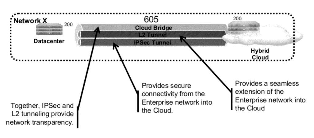
Embodiments in the present solution create a cloud-bridge to provide network transparency between networks that are otherwise dissimilar, such as those of the cloud service provider and datacenter. Appliances can be deployed both in the cloud and the datacenter. These appliances can be designed or constructed so that they communicate with one another and recognize and understand local IP and/or the public IP network information from the on-premises datacenter and cloud datacenter. These appliances can manage the network traffic flow between on-premise datacenters and cloud datacenters so that they appear and behave as a single network, spanning the cloud and on-premise datacenters.

Background for Systems and Methods for Cloud Bridging between Intranet Resources and Cloud Resources
Enterprise organisations may want to benefit from cloud computing, but they don’t want to give up on their own datacenters. This suggests a hybrid strategy, which is a mix between public and private cloud. To succeed with hybrid clouds, there are several challenges to overcome. The first is the complexity of applications. Enterprise applications rely on shared services such as directories and databases that reside on premises. These applications must work in the cloud, without migrating the shared services or duplicating them. Second, IT silos are a challenge. Although the on-premise datacenters and cloud are distinct infrastructure environments it can be difficult to avoid creating duplicate tools, processes, or teams. Third, secure and private connectivity is a challenge. “Incompatible network policies, misaligned IP addresses and other issues must be resolved to allow applications to run in both on-premises and cloud environments.
To address these challenges, enterprises can extend their networks to cloud datacenters located off-premises. Cloud-hosted apps are made to appear on enterprise networks by the cloud bridge. This is done for administrators, tools, and even applications themselves. The cloud environment can be extended to an enterprise datacenter by using the present solution.
Embodiments in the present solution create a cloud-bridge to bring network visibility between the disparate networks of datacenters and cloud service providers. The present solution creates an cloud bridge between the network of the cloud service provider and that of the datacenter. Appliances can be installed in both the datacenter as well as the edge of cloud. These appliances can be designed or constructed so that they communicate with one another and recognize and understand local IP and/or the public IP network information from the on-premises datacenter and cloud datacenter. These appliances can manage network traffic flow between on-premise datacenters and cloud datacenters so that they appear and behave as a single network that spans both on-premise datacenters and cloud datacenters. Cloud bridging is a feature of the solution that allows a variety of scenarios. Intranet-based devices can seamlessly access cloud resources, and cloud-based devices can seamlessly access intranet resources.
In one scenario, cloud bridging may involve appliances configured at either end of the bridge for a single tenant and no Virtual Local Area Networks. In this embodiment, the cloud bridge can be used to connect a single enterprise premises with no VLANs. All the networks directly connected to the appliance will then be extended to the cloud. The user can go to the client located on the local network and enter a uniform resource locator URL to the domain name or IP of another device within the cloud datacenter. The cloud bridge allows the client to directly access cloud-based resources identified by the URL. The user can go to the client in the cloud’s local network and enter a uniform resource locator URL to the domain name or IP of another device on the intranet. The cloud bridge solution allows the client to directly access intranet resources identified by the URL.
In another scenario, where cloud bridging is used, appliances may be configured at either end of the cloudbridge for a single tenant and no Virtual Local Area Networks are identified. Appliances may be configured for traffic management. The first appliance of the cloud bridge could have a virtual server for load balancing, content switching and two services configured: one on the local datacenter network and the other on or migrated on to the cloud local network. The user can go to the client located on the local network and type in the browser the uniform resource locator URL to the domain name or IP of a resource, such as a website. Web pages may contain URLs for resources in the cloud, on the intranet or on different VLANs. These resources are displayed as the web page is displayed or refreshed. They span the intranet, cloud and different VLANs.
In a second scenario, where cloud bridging is used, appliances at either end of the bridge can be configured to support multiple Virtual Local Area Networks. From one datacenter located on premises to another in the cloud, multiple customer networks can be extended. Appliances can be configured for customers A,B and C using VLANs, net bridges, and net bridges, respectively. Each customer can have their own cloud bridges. Appliances may use virtual servers based on load balancing/content-switching listen policies for each customer. Cloud bridging appliances respecting multi-tenancy VLANs for each customer provide seamless cloud bridging to each tenant, while also providing security for their respective networks when viewed in the context of the extended networks for the other tenants.
In some aspects, this solution is a method and system for accessing services across a network of private networks and cloud networks. A network bridge is established by a first intermediary device for a private networking and a second device for a cloud-based network using a secure IP layer. The network bridge extends IP addresses from the private network to cloud networks. The first intermediary device runs a virtual server that manages a service offered by a plurality servers in both the private and cloud networks. A first set of servers from the plurality are running in the private and cloud networks, and a second group of servers is running in the cloud. The virtual server received an access request from a private network client to the service identified by the internet protocol address. The first intermediary device transmits the request via the networkbridge in response to the virtual server to one of the servers of the second set.
In some embodiments, a virtual server receives a request from a client to access a service that is identified by an internet protocol address on the private networking. The virtual server instructs the first intermediary device to transmit the second request via the networkbridge to one of the servers from the first set in the private network.
The client receives an HTML page that contains uniform resource locators for resources in the private network as well as resources in the cloud, and displays both on this page.
In some embodiments, first and second intermediary device establishes the secure IP layer by establishing IPsec communication over a Layer 2 tunnel. In some embodiments the first and the second intermediary devices create the network bridge in order to extend the virtual local area networks (VLANs) of the private network onto the cloud network.

In some embodiments, a first intermediary device runs the virtual server in order to manage the service. This is done by load-balancing the service between the private network network and cloud network. In some embodiments, a first intermediary device runs the virtual server in order to manage the service. This is done by switching the traffic between the private network network and cloud network. In some embodiments the virtual server determines that the request matches the listening policy containing a predetermined virtual area network (VLAN identifier).
In some embodiments the second intermediary receives the response from the server on the cloud and sends it to the first intermediate device. The response includes the IP address for the client in the private network. The virtual server transmits the response to a client on the private networks.
The present solution is a system or method that provides multi-tenant network access to both a private network as well as a cloud network. The first intermediary deployed for a network private executes a plurality of virtualized engine packet processors. Each virtualized engine from the first plurality corresponds to one tenant in a plurality to be served by the first intermediate device. A second intermediary deployed for a network of cloud computing executes a second grouping of virtualized packet processors. Each virtualized engine from the second plurality establishes a network over a secure IP Layer tunnel with the corresponding engine from the first plurality. The network bridge extends IP addresses from the private network to cloud network. The first intermediary device, which is a virtualized packet processor engine, receives a demand from a device belonging to a tenant. The request identifies the virtual local area network (VLAN), which corresponds to the first tenant. The network bridge transmits a request from the virtualized packet processor on the first intermediary device via the virtualized packet processor on the second intermediate device.
In some embodiments, a virtual server may be operated on each virtualized engine of the virtualized engines of the plurality. Each virtualized engine in the first plurality can be operated by a virtual server. The virtual server can include a listening policy that identifies a virtual local network (VLAN), of a tenant of the plurality.
In some embodiments, first and second intermediate devices establish each secure IP-layer tunnel by establishing IPsec communication over a Layer 2 tunnel. In some embodiments the first and second intermediate devices establish each bridge to extend the virtual local area networks (VLANs) of the tenant’s private network to the cloud network.
In some embodiments, the virtual server running on the first virtualized engine for packet processing, matches the listening policy containing a predetermined virtual area network (VLAN identifier) of the tenant.
In some embodiments, a device receives a webpage containing uniform resource locators for resources on a private network as well as resources on s cloud network. The device then displays both resources from the private network on its web page.
The virtualized packet processor of the second intermediate device receives the response to the query, which identifies the IP address of that device on the private networking. The virtualized packet processor of the second intermediate device determines that the answer to the request matches the listening policy containing a predetermined virtual area network (VLAN identifier) of the tenant. The second intermediary transmits the response via the network bridge that connects the virtualized packet processor engine of the corresponding virtualized device to the virtualized engine of the first device.
The description and accompanying drawings show the details of different embodiments of the invention.
The following sections of the specification with their respective contents can be useful for reading the descriptions of various embodiments:
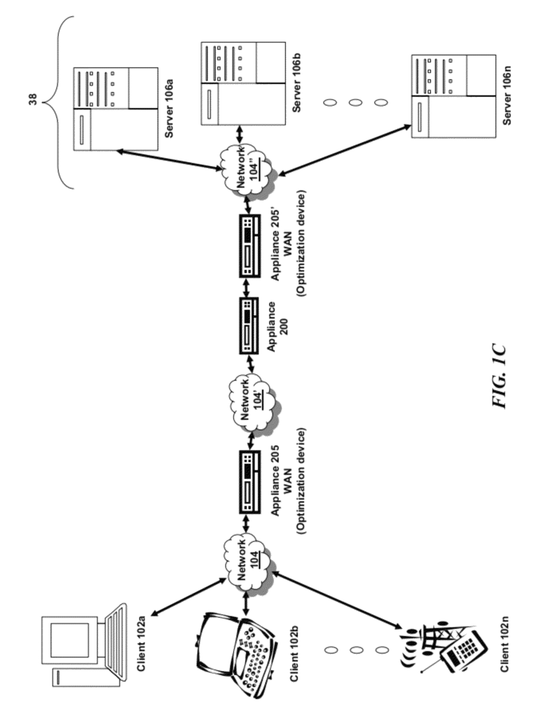

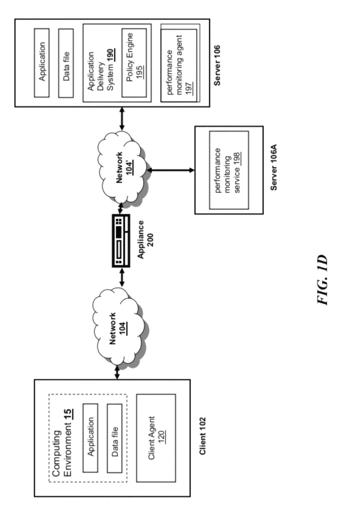
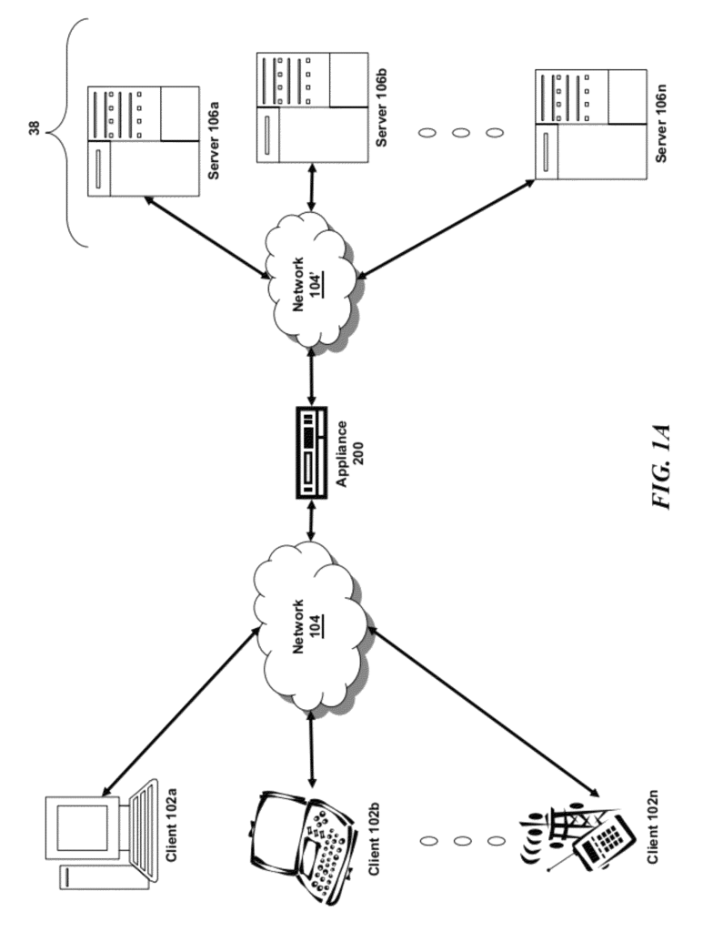
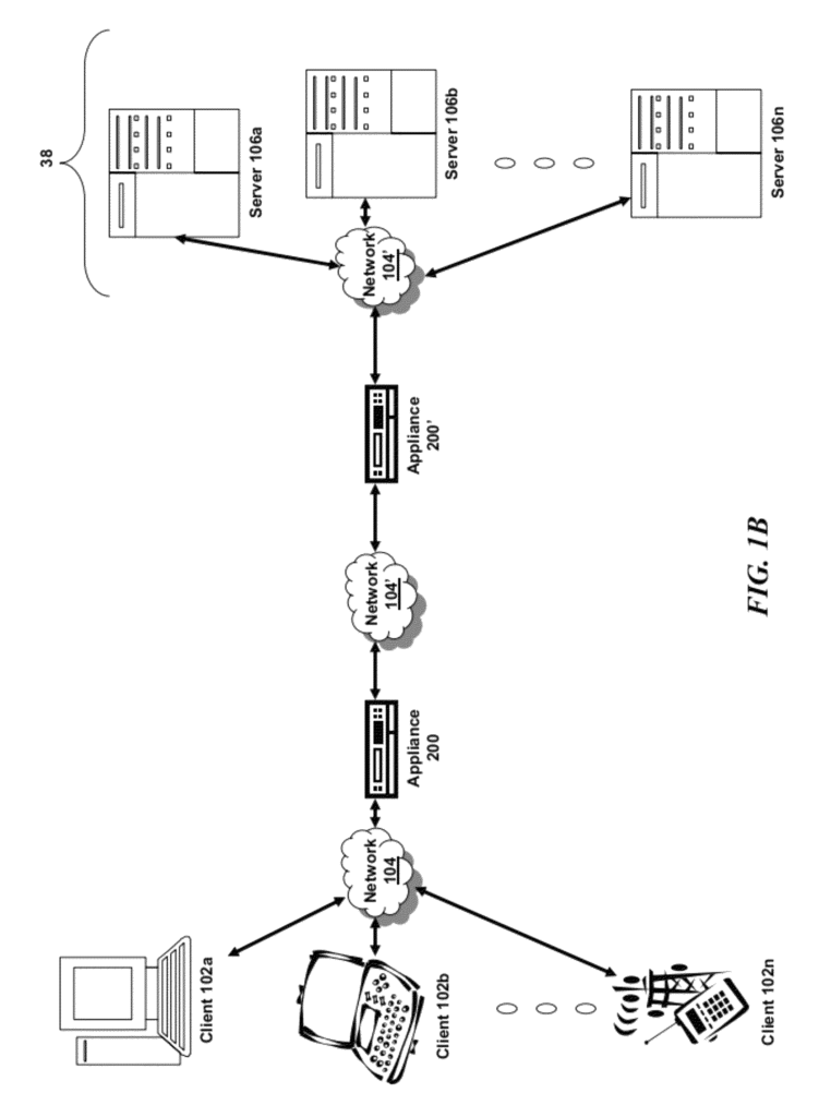
Before discussing the specifics about embodiments of systems and methods for a cloudbridge, it might be useful to discuss the computing and network environments in which these embodiments could be deployed. Now, let’s look at FIG. In FIG. 1A, a particular embodiment of a networking environment is shown. Briefly, the network environment consists of one or multiple clients 102a-102n (also commonly referred as local machine(s), or client(s), 102) that are in communication with one-or-more servers 106a-106n (also commonly referred as server(s), or remote machine(s), 106) through one or several networks 104. (generally known as network 104). In certain embodiments, the client 102 can communicate with a server via an appliance 200.