Invented by Jeffrey Koga, Cody D. Clifton, Zhenyi Wei, Grant Wildgrube, Oshkosh Corp
The Oshkosh Corp invention works as follows
A system of digital twinning a waste vehicle includes a waste vehicle and a control panel. The refuse vehicle is equipped with a sensor, device and electronic control system. The controller is configured for receiving multiple datasets, at least from one of the sensor device and electronic control system. The controller can also generate a virtual vehicle for refuse based on a plurality of datasets. The virtual refuse vehicle comprises a visual representation and multiple datasets of the refuse vehicle. Each of the many datasets is mapped to one of either the sensors or electronic control systems. The controller is configured for a display on a user device that provides a visual representation of the vehicle as well as one or more datasets.

Background for Systems for a virtual refuse truck
The present invention relates in general to the field relating to refuse vehicles and, more specifically, the field relating to digital twinning.
One embodiment is a digital twinning system for a refuse vehicle. The system consists of a refuse truck and a controller. The refuse vehicle is equipped with a sensor, device and electronic control system. The controller can receive multiple datasets either from the device or sensor. The controller can also generate a virtual vehicle for refuse based on multiple datasets. The virtual refuse truck includes a visual image of the refuse truck and the multiple datasets. Each of the many datasets is mapped to a sensor, a device or an electronic control system. The controller is configured for a display on a user device that provides a visual representation of the vehicle as well as one or more datasets.
Another embodiment” relates to a display method of information for a refuse vehicle. The method comprises obtaining multiple datasets using a sensor, device or system of the refuse truck. The method includes also generating a virtual twin of the refuse truck. The digital twin contains the multiple datasets as well as a graphic representation of the refuse truck. Each dataset is mapped with a sensor, device or system. The method includes also receiving a request at a user-device to display the digital version of the refuse vehicle. The method includes operating the display of the device in order to present the graphical representation and one or multiple datasets of the refuse vehicle.
Another embodiment is a cloud computing device for multiple refuse vehicles. Cloud computing system comprises a cloud device with a processor. The cloud device’s processor is configured to wirelessly connect with multiple refuse vehicle control units to obtain data on each refuse vehicle. The multiple refuse vehicle controllers, which are each positioned at the local level of a specific refuse vehicle, are designed to collect chassis, body, and third-party information from the sensors, systems or devices of that vehicle. The cloud device processor is configured to create a digital replica of each of the multiple vehicles based on the operational data. The digital twin contains a graphic representation of the corresponding vehicle, as well as the operational data for that vehicle. Cloud computing system includes a user-device with a processor, and a display. The cloud computing system also includes a user device with a processor and a display.
This summary is intended only as an example and not to be limiting in any way. The detailed description of the inventions or processes will reveal other aspects, inventive features and advantages.
Before turning to the figures that illustrate the exemplary embodiments, it is important to understand that the application does not limit itself to the specifics or methodologies described in the description, or shown in the figures. The terminology used is only for description and not to be taken as restrictive.
Referring to FIGURES in general, various embodiments of a virtual refuse-vehicle system are illustrated. The virtual refuse system includes a control unit configured to receive data from sensors or control units located in different locations on the refuse vehicle. The controller can be placed in any location suitable on the refuse vehicle. The controller receives and processes the information, and then transmits it to a remote computer via the wireless radio. The remote server contains a virtual refuse truck that receives information from the controller, and models it on the virtual refuse truck. The virtual refuse car is a virtual replica of the refuse truck and can be accessed by various applications via the remote server. Personal computer devices can access the virtual refuse vehicles to view a live feed of the refuse vehicle and to write time series data of the virtual refuse vehicles to a remote server. In some embodiments the virtual refuse truck may be accessed via a computer device that has administrative access. The controller may receive commands from the personal computer through the wireless radio and remote server. The commands sent to controller can be commands that correspond to the control unit and adjust the operation of control units in the refuse vehicle.
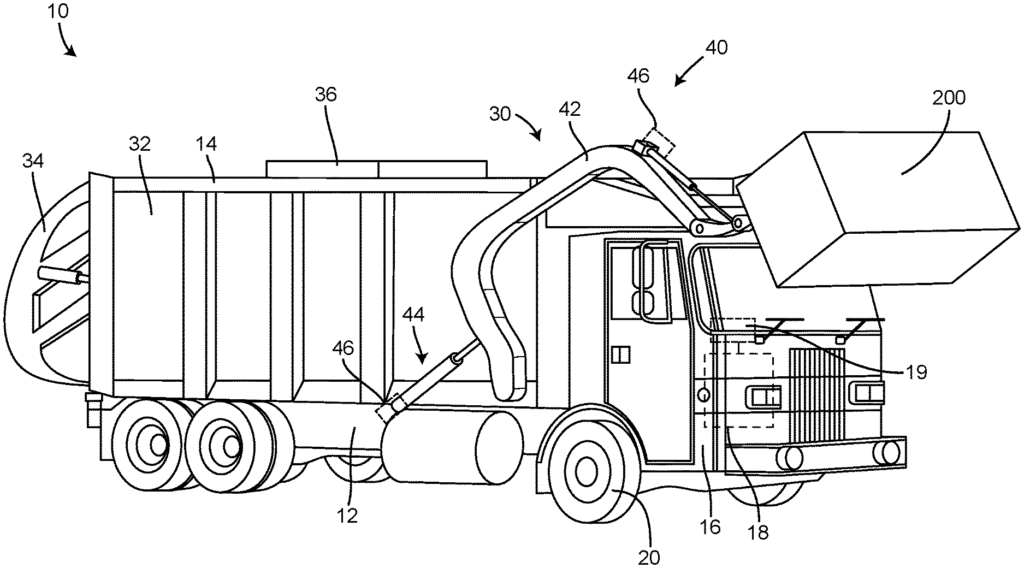
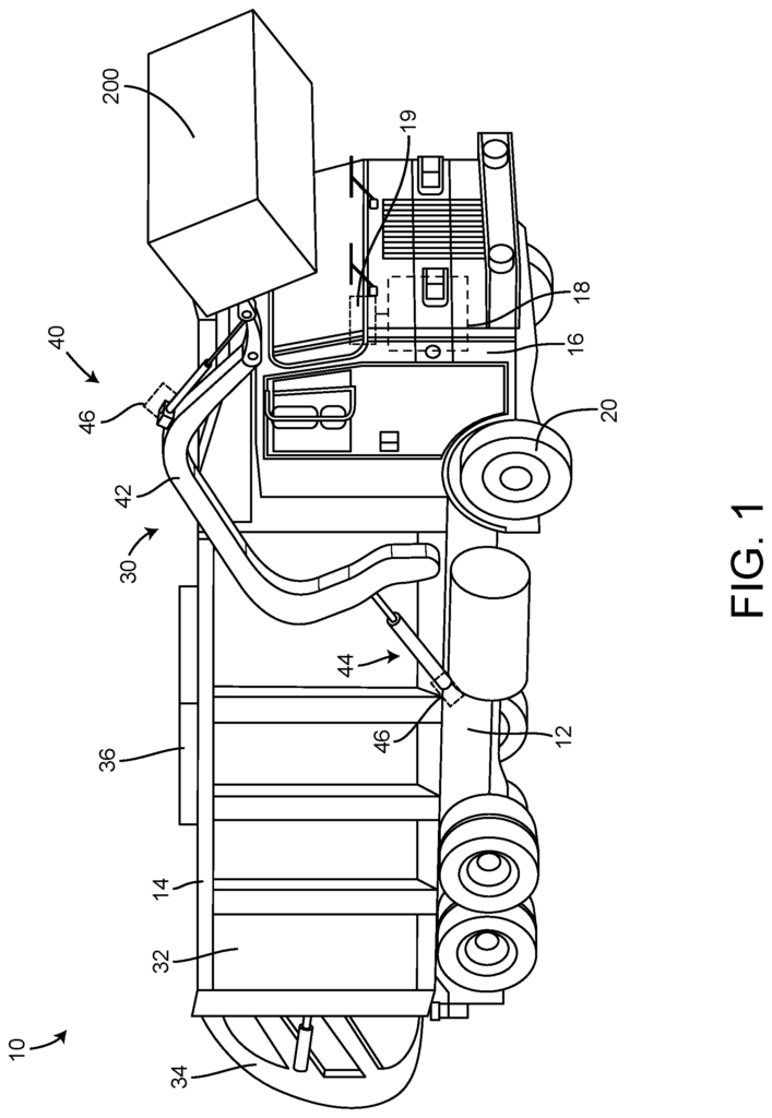
Accordingly, the exemplary embodiment is shown in FIGS. A vehicle is shown as refuse vehicle 10, which can be a garbage truck or a waste collection vehicle. The vehicle is designed as a front loading refuse vehicle. In other embodiments the refuse vehicle 10 can be configured as a front-loading vehicle or a zero-radius side-loading vehicle. In other embodiments, it is a different type of vehicle, such as a skid loader, a Telehandler, or a plow, boom, or telehandler. As shown in FIGS. The refuse vehicle 10 is shown in FIGS. The refuse vehicle 10 includes a chassis, shown as frame 12, a body assembly, shown at body 14, coupled to the framework 12 (e.g. at its rear end, etc.). The cab 16 can include various components that facilitate the operation of the refuse vehicle by an operator. (e.g. a seat and steering wheel, hydraulic controls or a user interface; an accelerator pedal, brake pedal, clutch pedal, gear selector, switches buttons dials etc.). As shown in FIGS. The refuse vehicle 10 comprises a prime mover (shown as engine 18) coupled to the frame 12, at a location beneath the cab 16, in FIGS. The engine 18 can be configured to power wheels 20 and/or other systems on the refuse vehicle 10. The engine 18 can be configured to use one or more fuels, such as gasoline, diesel bio-diesel ethanol natural gas etc. According to different exemplary embodiments, the engine 18 may be configured to utilize one or more of a variety of fuels (e.g., gasoline diesel bio-diesel ethanol natural gas etc.). In an alternative embodiment, one or more electric engines are coupled to the frame 12, such as in a hybrid refuse truck, electric refuse truck, etc. Electric motors can be powered by an onboard storage device, such as batteries or ultra-capacitors. The electric motors may be powered by an onboard generator, such as an internal combustion engine. The power can also be supplied by an external source, such as overhead power lines. And provide power to all the systems on the refuse vehicle 10.
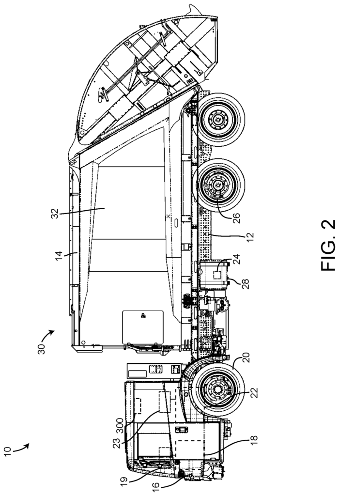
According to one embodiment, the refuse truck 10 is configured to transport waste from different waste containers within a municipal to a storage facility and/or processing facility. FIG. As shown in FIG. The panels 32 and tailgate 34 define a collection area (e.g. hopper). The refuse compartment 30 is shown. The refuse compartment 30 can be used to store loose refuse, which is then compacted. The refuse compartment 30 can be used to temporarily store refuse while transporting it to a disposal site or recycling facility. In certain embodiments, the refuse compartment 30 and at least a part of the body 14 extend forward of the cab 16 in some embodiments. FIG. 1 shows an embodiment. The body 14 and refuse compartment 30 is positioned behind cab 16. The refuse compartment 30 may include a hopper and a storage area in some embodiments. The refuse can be first loaded into the hopper and then compacted in the storage volume. In an exemplary embodiment the hopper volume is located between the storage volume, and the cab 16. (e.g. refuse is stored further to the rear of refuse compartment 30, after it is loaded in the position behind the cab). In other embodiments the storage volume may be positioned between a hopper volume, and the cab 16. (e.g. a rear-loading waste vehicle, etc .).
As shown in FIG. The refuse vehicle 10 has a first lifting mechanism/system, such as a front loading lift assembly. Lift assembly 40 is shown. The lift assembly includes a pair, shown as lift arm 42, which are coupled to either the frame 12 or the body 14 of the refuse vehicle 10, such that the arms 42 extend in front of the cab 16. In some embodiments, lift assembly 40 extends to the rear of the body 14. (e.g. a rear-loading vehicle for refuse, etc.). In other embodiments the lift assembly extends outward from the side of the vehicle 14 (e.g. a side loading refuse vehicle). The lift arms 42 can be pivotally coupled to the frame 12 (e.g. a lug or shaft). As shown in FIG. As shown in FIG. 1, the lift assembly includes first actuators (shown as lift arm actuators 44, e.g. hydraulic cylinders etc.). The frame 12 and lift arms 42 are connected by the lift arm actuators 44. According to one embodiment, the lift arm actuators are positioned so that the extension and retraction of the lift arms 42 is rotated about an axis running through the pivot. Lift arms 42 can be removable coupled to a container. In FIG. 200, the container is shown as a refuse container. 1. In certain embodiments, lift arm 42 includes a pair grabber fingertips rotatably attached to lift arms and configured to rotate around an axis that extends through the pivot point of each grabber finger. Grabber fingers can rotate around the axis that extends through each grabber finger’s pivot point to grasp a waste container. The lift arms 42 can then rotate around the axis that extends through the pivot point to empty the contents of the container into the refuse compartment 30.

Referring back to FIGS. According to an example embodiment, the refuse vehicle 10 includes an engine control module (shown as engine control unit, or ECU), which is represented by engine control unit 19. ECU 19 can be configured to communicate with engine 18 while controlling engine operations. ECU 19 may, in some embodiments connect with engine 18 sensors and control the operation of actuators. Sensors that ECU 19 can connect to include at least one of the following: an air flow or mass airflow sensor; a pressure or temperature sensor; an engine speed sensor; an exhaust oxygen sensor; a throttle position and temperature sensor. ECU 19 can receive information from one or more sensors, and determine the adjustment to be made for engine 18. ECU 19 can include a processing and memory circuit configured to receive information from sensors via a communication interface. ECU 19 could use a lookup chart, an equation or set of rules stored in its memory to determine engine 18’s operational adjustment. ECU 19 can be configured to implement engine 18’s operational adjustment by sending signals to controllers that are configured to adjust at least one of the following: a fuel injector quantity, a timing, an air-to-fuel ratio, idle speed, valves of the engine, etc.
Referring to FIG. According to an example embodiment, the refuse vehicle 10 includes a gear system (shown as transmission 22) and a transmission module (shown as transmission control unit 23). Transmission 22 is configured for receiving a torque from engine 18 via a connecting shaft. It then adjusts the engine torque and supplies the adjusted engine torque to wheels 20. Transmission 22 can be a torque converter automatic, manual transmission or automatic manual transmission. It may also be a dual clutch transmission, direct shift gearbox, continuously variable transmission (CVT), a dual clutch transmission, or another torque converting device.
TCU 23 can receive information from sensors related to the operation of transmission 22 and control transmission 22 operations based on that information. TCU 23 can receive information from sensors such as cruise control systems, brake light switches, fluid pressure sensors or kick-down switches, throttle position sensors, transmission fluid temperature sensors, turbine speed sensors, input speed sensors, wheel sensors, etc. TCU 23 can receive information from one or more of the sensors/systems, and based on that information determine the adjustment of transmission 22. TCU 23 can include a processing system and memory that are configured to receive information from sensors/systems via a communication interface. TCU 23 could then use a lookup chart, an equation or set of rules stored in its memory to determine the adjustment of transmission 22. TCU 23 can be configured to transmit signals to controllers or other devices such as a transmission lock, shift solenoids and pressure control solenoids.
Referring to FIG. According to one embodiment, refuse vehicle 10 includes lift assembly sensors. Lift arm sensors 46 are shown. Lift arm sensors are placed at any point where the lift assembly is designed to pivot. Lift arm sensors are configured to measure an angle at which a pivot point is located on lift assembly 40. Lift arm sensors 46 can be used to measure the amount of hydraulic fluid that has entered or left a chamber of lift actuators 44.
Referring to FIG. According to one embodiment, refuse vehicle 10 includes a fuel sensor (shown as fuel level sensors 24) and a sensor for wheel speed (shown as wheel speed sensors 26). In some embodiments the wheel sensor can be or include a tire-pressure sensor. Fuel level sensor 24 may include a variable resistance configured to change its resistance when the fuel level in a tank (shown as fuel tank 28) changes. Wheel speed sensor 26, according to different embodiments, may be a magneto-resistive sensor or a magnetic inductive one. It is configured to measure a speed, such as a rotational speed, linear speed at a diameter (or other) of wheel 20. Wheel speed sensor 26 may be a magnetic inductive sensor, or a magneto resistive one, according to various embodiments. It is configured to determine a speed (e.g., determining if he wheel 20 has accelerated linearly at d diameter)
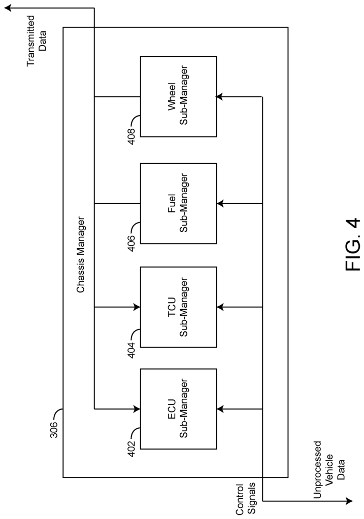
Referring to FIG. According to one embodiment, the refuse vehicle 10 includes a central module shown as controller 300. The controller 300 can receive data from any control module, including but not limited to ECU 19, TCU 23 etc. Sensors (e.g. wheel speed sensor 26, Fuel level sensor 24 etc.). Referring to FIGS. According to one embodiment, FIGS. Controller 300 can be connected to any electronic module or sensor in refuse vehicle 10, such as but not limited to ECU 19, TCU 23 a Powertrain Control Module, Brake Control Module, Central Control Module, Central Timing Module, General Electronic Module, Body Control Module, Suspension Control Module, ABS/traction control/stability module (SRS), an airbag module (SRS), an anti-theft, cruise control, electronic steering, fuel pump module and injector driver, instrument cluster module control, lighting module control, Any of the electronic control modules listed above can also receive inputs from sensors located around refuse vehicle 10. The controller 300 can be connected to the modules listed above, so that it monitors all information received or sent by the modules listed above. In some embodiments controller 300 can be configured only to monitor/receive the information sent/received from any of modules listed above. However, in other embodiments controller 300 can also be configured to adjust the operation of any module listed above.
Controller 300 can be configured to receive data regarding the chassis of the refuse truck 10 (e.g. ECU 19, TCU 23 etc.). ), a body of the refuse vehicle 10 (e.g., pneumatics, hydraulics, sensors, cameras, electronics, Human-Machine-Interface (HMI), GPS, etc. According to an exemplary embodiment, the refuse vehicle 10 includes a body (e.g. pneumatics, hydraulics, sensors, cameras, electronics, Human-Machine-Interface (HMI), GPS, etc.), a third party system (e.g. an object detection system or driver behavior system (ADAS), a security system, a weigh system, etc.), and a third party system (e.g. an advanced driver assistance system (ADAS), a safety device, a weight According to a exemplary embodiment, controller 300 receives information from the chassis of the vehicle and the body of a vehicle through an infrastructure already present on refuse vehicle 10. In an exemplary embodiment the controller 300 receives data from the chassis and body of the vehicle via an infrastructure that is already present in the refuse vehicle 10. Controller 300, for example, may be configured so that it can communicate with ECU 19 in order to receive information about engine 18 without the need to add additional sensors or systems. This allows the controller 300 to monitor/collect information from refuse vehicle 10 without having to install an additional sensor system.
Controller 300 can also receive information via a third-party system on refuse vehicle 10.” A third-party Global Positioning System device (GPS), for example, may be installed on refuse vehicle 10, and can communicate with controller 300. Other third-party systems include, but aren’t limited to, an object detection system (ODS), a driver behaviour system (ADAS), a security system, a weigh system, etc. According to one embodiment, Controller 300 can receive and monitor data from any of these systems.
Controller 300 can be communicably connected to any chassis, body and third-party systems, as described in the above paragraph with reference to FIGS. 1-2. In certain embodiments, the controller 300 can communicate with an onboard diagnostics system (OBD) of refuse vehicle 10 “For example, controller 300 can connect to the OBD II of refuse vehicle 10, and monitor/access information on that system.
In some embodiments controller 300 can be communicably connected to a vehicle of refuse vehicle 10. The vehicle bus for refuse vehicle 10 can be a Controller Area Network bus (CAN), a Local Interconnect Network bus (LIN), a Media Oriented Systems Transport bus (MOST), an SAE J1850 Bus, an Inter-Integrated Circuit bus (I2C), etc. or any other common automotive bus. The Controller 300 can be configured to communicate with the vehicle to monitor and receive information transmitted by the vehicle.


Referring to FIG. According to an example embodiment, a detailed block-diagram of controller 300 can be seen in Figure 3. According to an exemplary implementation, controller 300 includes a circuit (shown as processing circuit 302), a processor (shown as processor 305), and memory (shown as memory 304). Controller 300 may be implemented as a general-purpose processor, an application specific integrated circuit (ASIC), one or more field programmable gate arrays (FPGAs), a digital-signal-processor (DSP), circuits containing one or more processing components, circuitry for supporting a microprocessor, a group of processing components, or other suitable electronic processing components. The exemplary embodiment of FIG. The controller 300 comprises a processing circuit 302 as well as a memory. The processing circuit 302 can include an ASIC or one or more FPGAs or DSPs, circuits that contain one or multiple processing components, circuitry supporting a microprocessor or other electronic processing components. In certain embodiments, the processing circuit 302 can be configured to execute code stored in memory to facilitate activities described herein. Memory 304 can be any computer-readable medium, whether volatile or nonvolatile, capable of storing computer code or data relating to activities described in this document. In an exemplary embodiment of the invention, memory 304 contains computer code modules, such as executable code (e.g. object code), source code (script code), machine code (machine code), etc. The processing circuit 302 is configured to execute the code modules. Memory 304 contains various actuation profile corresponding to different modes of operation. According to one embodiment, memory 304 includes various actuation profiles corresponding to modes of operation (e.g., for transmission 22, drive system 100, for a vehicle etc.). In certain embodiments, the controller 300 can represent a group of processing devices, such as servers, data centres, etc. In these cases, the processing circuit 302 is the collective processors and the memory 304 is the collective storage devices.