
Invented by Szymon Piotr Stachniak, Hendrik Mark Langerak, Michelle BROOK, Microsoft Technology Licensing LLC
The Microsoft Technology Licensing LLC invention works as follows
An augmented-reality device comprises a logic device and a storage device containing instructions that can be executed by the logic device to fit a virtual plane of two dimensions to a real world surface represented in a 3-dimensional representation of an environment real of the augmented-reality device. The request is received to place a three-dimensional virtual object on the surface of a real-world. Each of the plurality of possible placement locations is evaluated to determine whether it is a valid or invalid location. “An invalidation mask that defines valid and invalid locations on the two-dimensional virtual plane is generated.

Background for Virtual object positioning for augmented Reality
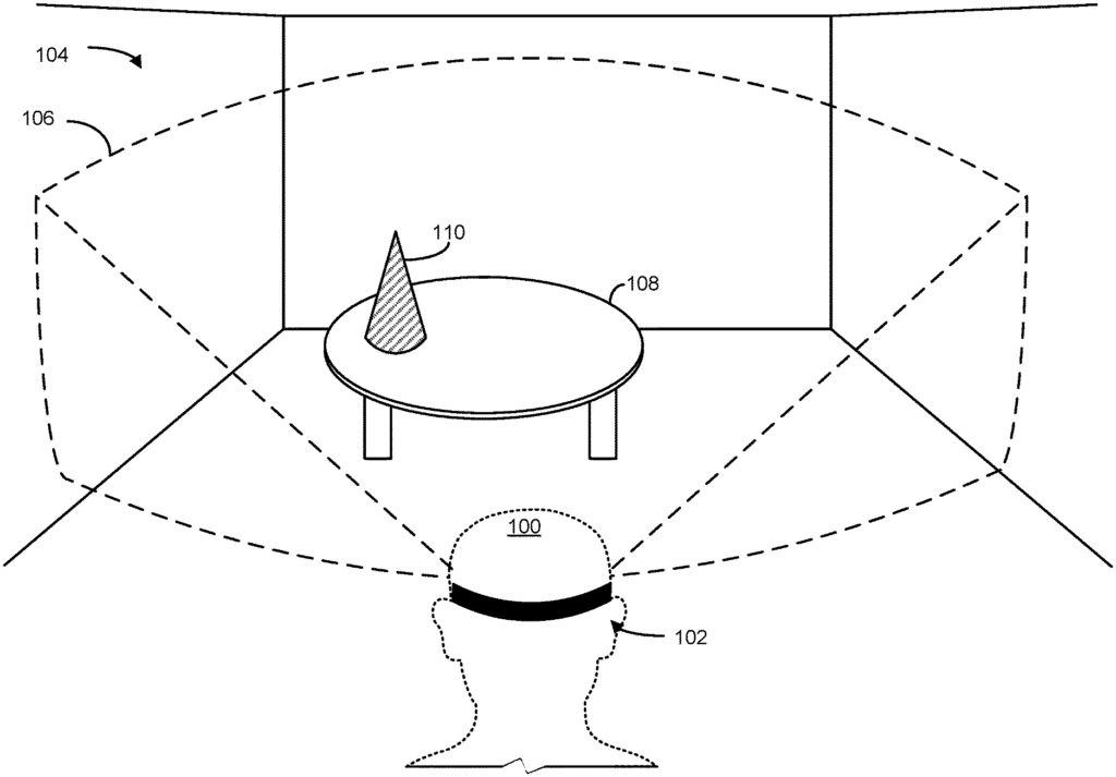
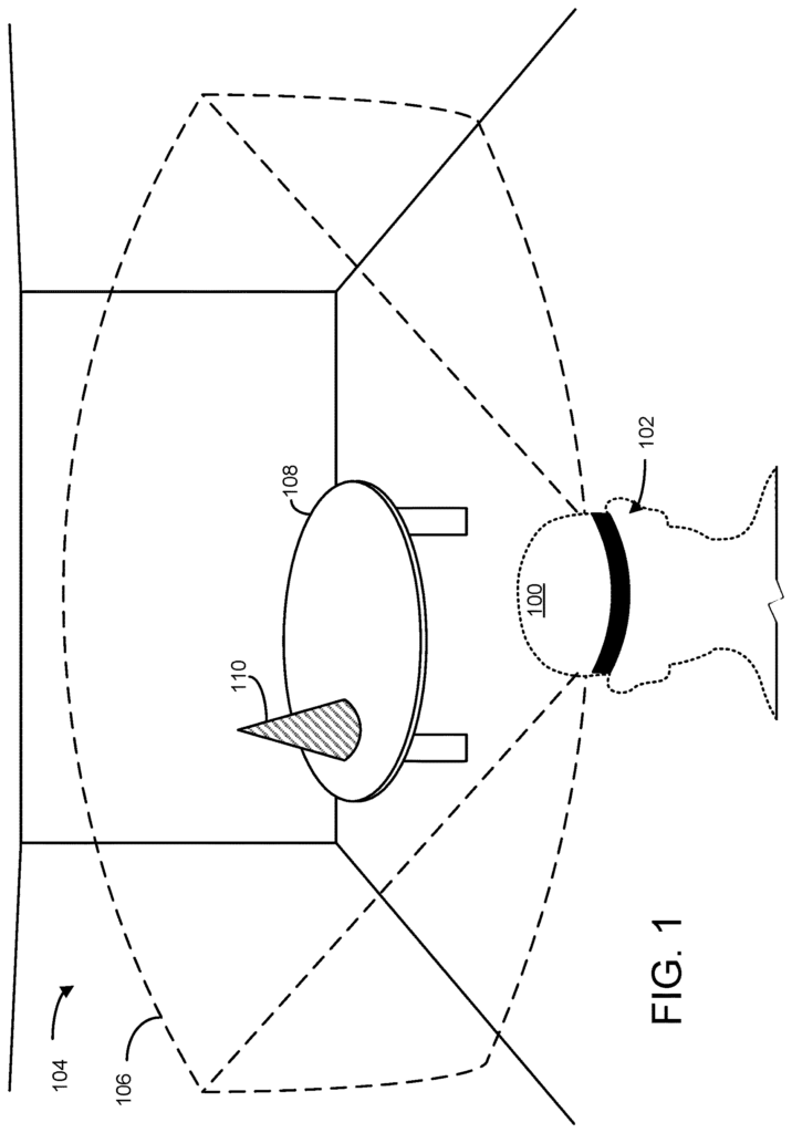
Virtual objects can be displayed via portable or stationary display devices. This includes head-mounted displays (HMDs). These devices can be used for augmented reality (AR), virtual reality (VR), and other experiences. “The virtual imagery can be rotated, resized and/or moved based on the user’s input.
This Summary is intended to present a number of concepts that will be further explained in the detailed description. This Summary does not aim to identify the key features or essential elements of the subject matter claimed, nor to limit its scope. The claimed subject matter does not limit itself to solutions that address all or some of the disadvantages mentioned in this disclosure.
An augmented-reality device comprises a logic device and a storage device containing instructions that can be executed by the logic device to fit a virtual plane of two dimensions to a real world surface represented in a 3-dimensional representation of an environment real of the augmented-reality device. The request is received to place a three-dimensional virtual object on the surface of a real-world. Each of the plurality of possible placement locations is evaluated to determine whether it is a valid or invalid location. “An invalidation mask that defines valid and invalid locations on the two-dimensional virtual plane is generated.
The augmented reality computing systems 200 may include sensors and other systems that provide information to an on-board computer. These sensors include but are not restricted to one or two inward-facing image sensors (210A, 210B), one or both outward-facing image sensors (212A, 212B), an inertial measuring unit (IMU), 214 and one or all microphones 216. The one or two inward-facing image sensors 210A and 210B can be configured to obtain gaze tracking data from the wearer (e.g. sensor 210A could acquire image data of one eye, while sensor 210B could acquire image data of the other eye).
The on-board computer may be configured in a suitable way to determine the gaze direction of each wearer’s eye based on information received from image sensors 210A and 210B. The on-board computer and one or more image sensors facing inward 210A,210B may be collectively represented as a gaze detection device configured to determine the wearer’s target gaze on the near-eye 202. In some implementations, another type of gaze sensor/detector may be used to measure one of more eye gaze parameters. One or more gaze sensors may measure a variety of gaze parameters that can be used by on-board computer (204) to determine eye gaze samples. These include eye gaze direction and head orientation. Also, they may measure eye gaze velocity, acceleration, changes in eye gaze angle, etc. Eye gaze tracking can be recorded separately for each eye in some implementations.
The one, or more, outward-facing image sensors 212A and 212B can be configured to measure the physical environment attributes in a physical space. Image sensor 212A, for example, may be a visible light camera that is configured to capture a visible light image of a space. The augmented reality computing systems may also include a pair of stereoscopic visible-light cameras. The image sensor 212B can also include a camera that collects a depth picture of a space. In one example, the infrared depth camera is a time-of flight depth camera. Another example is the infrared structure light depth camera.
Data from the outward-facing image sensors 212A and 212B can be used by the computer on board 204 to detect movement, such as gestures-based inputs, or other movements performed either by the wearer, or by another person or object in the real space. In one example data from the outward-facing image sensors 212A and 212B can be used to detect wearer inputs performed by the wearer, such as gestures. The on-board computer may use data from the outward-facing image sensors 212A and 212B to determine direction/location, orientation, etc. (e.g. from imaging environmental features), which enables the position/motion tracking for the augmented reality system 200 within the real-world. In some implementations data from the outward-facing image sensors 212A and 212B can be used by on-board computer to create still images or video images of the environment from the perspective the augmented reality computing systems 200.
Click here to view the patent on Google Patents.