
Invented by Wei-Chih Chang, Mong-Yu TSENG, Nai-Jui CHENG, HTC Corp
The HTC Corp invention works as follows
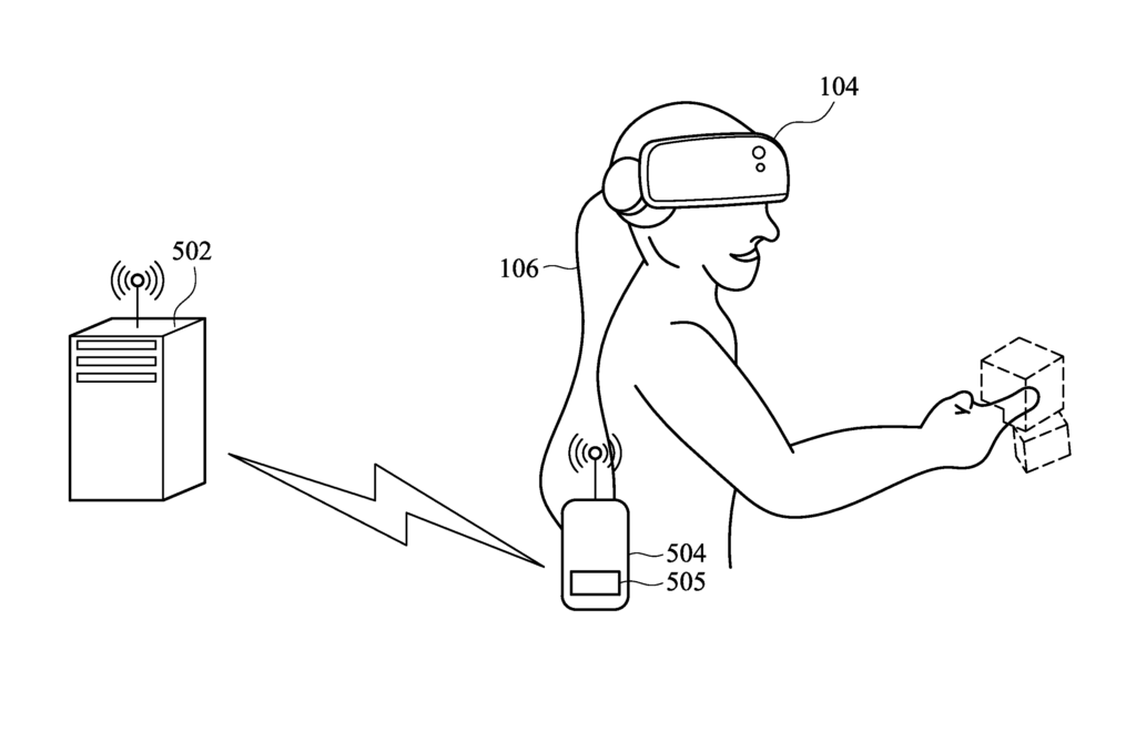
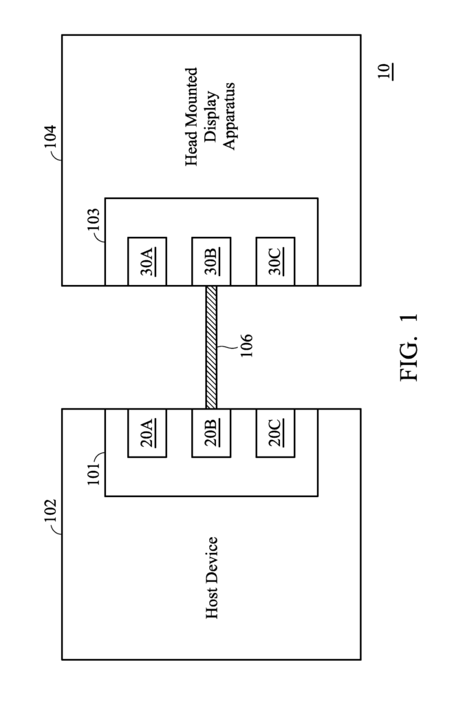
A virtual-reality system is provided.” A transmission cable connects a head-mounted display device to a host. Multimedia content is received by a multimedia module via the first signal path in the transmission cable. Multi-sensing modules obtain sensing information about the head mounted display device and the user. Power management device controls power status for the multimedia module and peripheral hub based on a power voltage through a third path of the transmission cord. “The microcontrol unit detects the mode in which the virtual reality system operates based on the signal status of first and second signals paths of transmission cable, to notify the powermanagement device to control power status for the multimedia module.

Background for Virtual Reality System and Method for Controlling Operation Modes of Virtual Reality System
Field of Invention
The invention is a virtual-reality system and, more specifically, a head-mounted display apparatus for virtual reality systems.
Description of Related Art
Near-to-eye displays, or display devices that are close to the eye, are frequently used with displays with virtual image generation. These display devices, such as head-mounted displays (HMD), are well known.
HMDs are display devices that people wear on their heads to view video directly in front of their eyes. Near-eye displays are another name for HMDs. HMDs can have one or two CRT, OLED or LCD displays. They also include magnifying lenses. Displays and optics can be embedded into a helmet or glasses. To prevent eye strain, lenses and other optical components give the impression that the images come from a distance. In HMDs with a single screen, the image is projected using optics which splits the image into two identical pictures and directs each one to its respective eye. HMDs with two displays can display stereoscopic pictures. The stereoscopic image attempts to simulate the angular differences between the images seen by each eye while looking at an object due to different positions of the two eyes. The angular difference between the images viewed by each eye when looking at an object is one of the main parameters that the brain uses to process images in order to create depth perception in human vision.
A virtual-reality system and a control method for the operating modes of a VR system are provided.” A virtual reality system embodiment is presented. Virtual reality system includes a host device and a transmission cord, as well as a head-mounted display device that is worn by the user and connected to the host via the cable. The head-mounted display apparatus consists of a multimedia unit, a multisensing device, a peripheral center, a power management system, and a microcontrol unit. The multimedia module receives content from the host via a transmission cable’s first signal path. The multi-sensing unit obtains information about the head mounted display device and the user. The peripheral hub transmits the sensing data to the host via a second path of signal transmission. Power management device controls the power status of multimedia module, multi-sensing modules, and peripheral hub based on a power voltage received from the host via a transmission cable’s third signal path. “The microcontrol unit detects the mode in which the virtual reality system operates based on the signal status of first and second signals paths of transmission cable. This is done to inform the power management device of power status for the multimedia module and multi-sensing modules, as well as the peripheral hub.
Furthermore is a method of controlling the operation modes in a virtual-reality system. Virtual reality system consists of a host device that is worn by a user, a head-mounted display device, and a cable connecting the host device to the head-mounted display device. When a power signal from the host device arrives, the head mounted display apparatus determines if a signal is present in the first signal path. When the first signal has been received, the head mounted display apparatus determines if a secondary signal exists in the second signal path of transmission cable. The head-mounted display apparatus controls the display to be in full operation when the first and second signals are present in the transmission cable’s first signal path. The head-mounted display apparatus controls the display to operate in mobile mode when a first signal is present in the first path of transmission cable, and a second signal does exist in the other path.
The following embodiments are described in detail with the drawings that accompany them.
BRIEF DESCRIPTION DES DRAWINGS
The following detailed description, examples and drawings with reference to the accompanying drawings will help you better understand the invention.
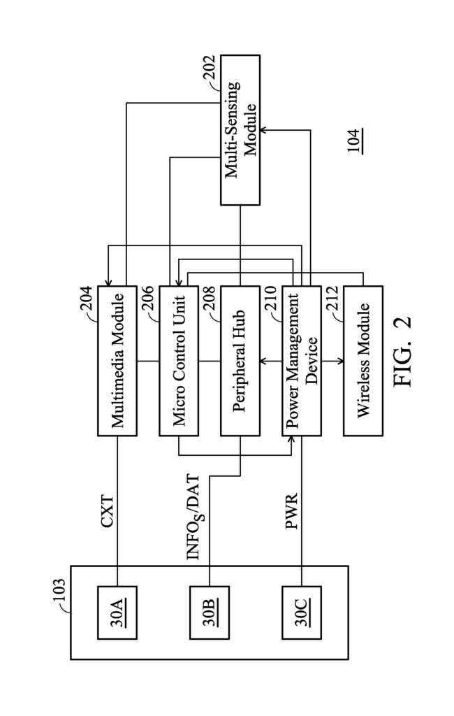

FIG. “FIG.
FIG. “FIG. “1 according to a particular embodiment of the invention
FIG. “FIG. “2 according to a particular embodiment of the invention
FIG. “FIG. “2 according to a particular embodiment of the invention
FIG. “FIG. “1 according to a particular embodiment of the invention
FIG. “FIG. “1 according to a particular embodiment of the invention
FIG. “FIG. 6A;
FIG. “FIG. “1 according to a different embodiment of the invention
FIG. “FIG. “1 according to another embodiment;
FIG. “FIG.
![]()

FIG. “FIG.
![]()
