
Invented by Wade F. Burch, Jeffrey M. Zeiler, Leslie J. Reading, Milwaukee Electric Tool Corp
The Milwaukee Electric Tool Corp invention works as follows
A power box and method for communicating through the power box are provided.” The power distribution box has a power input coupled to an output that provides power to external devices. The housing of the power box supports a gateway device that includes a wireless module to communicate with power tools, and a cell module to communicate via cellular network with an external power tool monitoring system. The gateway can be removed from the power distribution unit. The gateway contains a translation controller that enables communication to be established between the wireless module and external network via the cellular module. The translation controller is responsible for translating messages between power tools and the external network. The messages can include location data, operational data or data related to the power tool.

Background for Wireless Tracking of Power Tools and Related Devices
Theft and misplacement are major problems for power tool users. Power tools that are more expensive and of higher quality often have a greater chance of being stolen. Some buyers opt for lower-quality and cheaper power tools in order to minimize the risk of theft. It can also be difficult and time-consuming to check inventory on such tools periodically, say, at the end a day to make sure all tools have been returned. This burden is especially significant for companies that are responsible for maintaining large collections of tools.
In one embodiment of the invention, there is a box that includes a power input and an AC output. There’s also a power-line converter, and a gateway. The power input can be configured to receive power via an external source. The AC output is electrically connected to the power input. It is configured to supply power to external devices. The power-line is configured to receive power from the power input, and communicate with an external system. The gateway device includes a wireless networking module and a translator controller. It is connected to the power-line Adapter. The wireless module is configured to connect to at least one power tool in a wireless networking. The translation controller is connected to the power line adapter, enabling communications between the wireless module and external network via the power-line connector.
In a second embodiment, an invention is provided that includes a power input and a first output power, as well as a power-line converter and gateway device. The power input can receive power from external sources. The power output of the first device is electrically connected to the power input. It is designed to supply power to external devices. The power-line is connected to the input. It is designed to accept power from the input, and communicate with an external system. The gateway device, which is connected to the power-line Adapter, includes a wireless module, a cell module and a translator controller. The wireless module is designed to communicate wirelessly with at least one device of a power tool. The cellular module, on the other hand, is designed to communicate via a cellular system with an external network. The translation controller, which is connected to the power line adapter, wireless network and cellular modules, enables communication with the external network by using the power line adapter or the cellular device.
In another embodiment of the invention, it provides a way to communicate with at least one tool by using a box that includes a power-line converter, a gateway, and AC outlets. The method involves receiving AC power at the power input of the distribution box and distributing it to the AC outlets. The method also includes receiving wireless communication from a device that is a power tool, including operational data. This data is transmitted to the gateway device by the device.
The invention includes a tracking system for tools to assist with inventory management, to minimize and prevent misplaced and stolen tools, and to recover them on the jobsite. The detailed description of the invention and the accompanying drawings will reveal other aspects.
The invention can be embodied in other ways and is capable of being practiced or carried out in different ways. The invention can be embodied in other ways and practiced or carried out differently.
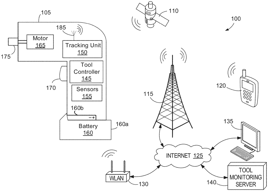
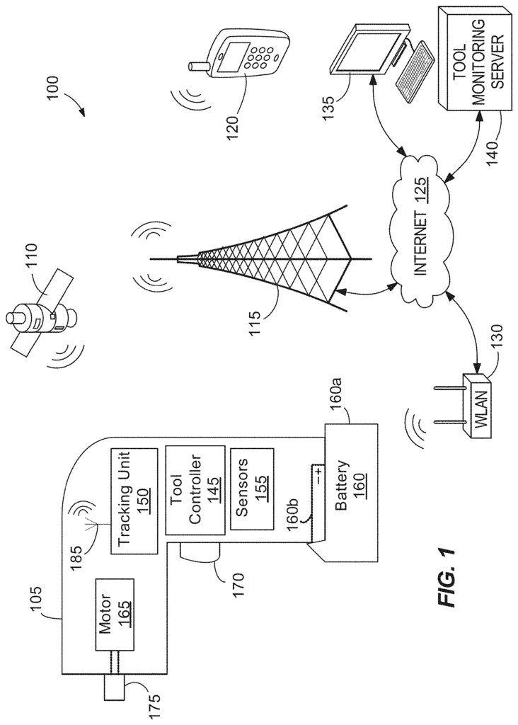
FIG. The tool monitoring system is shown in Figure 1. It includes a device 105, satellite 110 (representing the series of global positioning systems), a cell network antenna 115, Internet 125 and wireless router 130. The tool monitoring server 140 allows a user, via a smart phone or computer, to remotely monitor the status, usage and position of the tool.
The tool 105″ is a battery operated power drill consisting of a tool control 145, a tracking unit 150 and sensors 155. The battery 160 also contains a motor. The tool controller 145 applies power to the motor 160 from the battery to rotate the motor in response to depressing a trigger 170. The motor 165 rotates a bit that is held by an end output 175 (e.g. a bit holder) to drill a hole into a workpiece, drive in screws, etc. The motor 165 can be a brushless or brushed motor. It could also be a permanent magnet motor.
Even though the tool 105 appears to be a power drill in the illustration, the tool monitoring system can monitor other types of accessories and tools. The tool monitoring system 100 can monitor, for example, battery packs, chargers, power tools, radios at work sites, outdoor power equipment and vehicles. Power tools include drills and circular saws. They can also include jigsaws, bandsaws, reciprocatingsaws. Angle grinders are another type of power tool. Chargers for batteries can be wall chargers or multi-port chargers. They also come in travel chargers and other types. Test and measurement tools can include digital meters, clamp meters and fork meters. They may also include wall scanners and laser distance meters. Vacuum cleaners include stick vacuums and hand vacuums. They can also be upright vacuums. Outdoor power equipment includes blowers, hedge trimmers and trimmers, edgers (edgers), chainsaws, lawnmowers, trimmers. The battery pack is also attachable and removable from devices like electronic key boxes and calculators. It can be attached to or detached from headphone, camera, motion-sensing alarms and flashlights. The tool monitoring system 100 can monitor multiple devices at once.
The sensors 155 are used to detect different statuses and usage data from the tool. The sensors 155 can include, for example, a motor sensor that tracks the number of motor turns and detects motor rotation speed, acceleration, and torque, a battery sensor that detects the charge level of the battery and the rate at which it increases or decreases, a trigger sensor that detects whether the trigger has been depressed, an acceleration sensor, to detect movement, including sudden deceleration (e.g. caused by dropping), and a thermometer to detect temperature inside the tool housing.

The tool controller is in communication with sensors 155, receiving sensor data obtained from sensors 155. The tool controller can control the operation (e.g. to enable or disable certain sensors) of sensors 155. The tool controller includes a memory (see FIG. The tool controller 145 includes a memory 180 (see FIG.
The battery 160 is an energy storage device which can be removed and recharged. It provides power for the tools 105. The battery 160 can be made up of electrochemical cells, which convert chemical energy stored in the batteries into electrical energy. The battery 160 can include nickel-metal-hydride, lithium-ion and/or Nickel-cadmium cell types. You can also use other battery cells. Battery 160 has a base (160 a) and a projection (160 b) with a positive and negative electrical contact. The projection 160b slides into the receiving cavity at the bottom of the handle 105, locking into engagement. This ensures that the battery is locked into place with the tool until a release button (not shown) has been pressed. Other battery configurations and connections are possible in some embodiments for the tool 105 that includes an internal, nonremovable battery.
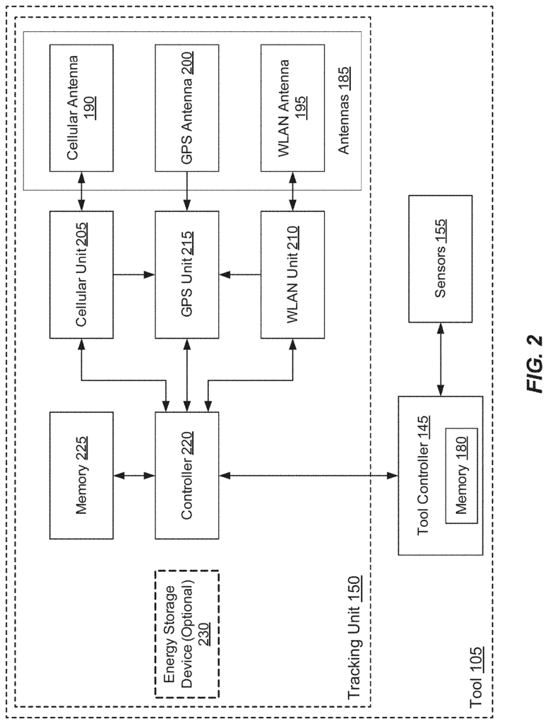
Rotating the motor 165 can cause interference which is detrimental to the performance of at least one of the antennas. In some embodiments, the tracking unit 150 delays transmissions if the motor is spinning. Transmissions that are of high priority (for example, to alert the user of a possible theft) are not delayed. The tracking unit 150 will not delay transmissions if motor 165 continues to rotate for an extended period of time, especially if battery 160 is low. The antennas 185 can also be placed in the tool 105, away from possible sources of interference such as the motor. The antennas 185 can be placed at the bottom of the tool 105’s handle. One or more antennas 185 can be integrated into a housing, gear case or other component of the tool 105 in order to improve the transmission and reception performance.
The tracking device 150 also includes a controller 225 in communication with cellular unit 220, WLAN unit 210 and GPS unit 215. It is also equipped with a memory 225. The memory 225 can store instructions which, when executed by controller 220, allow the controller to perform the functions attributed to controller 220 as described in this document. In some cases, the tracking unit is powered by a battery 160. The tracking unit 150 can operate without the battery 160 if the additional energy storage device is 230. The tracking unit 150 can operate on the power of the additional energy storage 230 if there is no battery in the tool 105 or the battery is below the low power threshold. The controller 220, for example, may receive an indicator from the tool controller that the battery is not present in the tool 105 or below a threshold of low power. The controller 220 can then open or close the switch (not shown), which connects the energy storage device to the other components in the tracking unit.
The additional battery 230 is a primary, non-rechargeable battery which cannot be removed from the power tool, except for repairs. The primary battery can have a lifespan of five to seven year in some cases. The primary battery, for example, may be mounted or soldered to a printed-circuit board that also includes other components of tracking unit 150. In some embodiments the additional energy storage unit 230 may be a lithium-ion rechargeable battery and/or ultra capacitor. In some embodiments the tracking unit may be powered, either in conjunction with or instead of other power sources, by a fuel-cell within the tool, and/or an externally mounted solar cell.
The controller 220 also communicates with the tool control 145 to, for example, retrieve tool usage and status data that is stored in memory 180, or is obtained by the tool control 145 in real-time (e.g. from the sensors 155).
The tracking unit 150 receives GPS signals from satellite 110 via the GPS antenna 200. GPS signals are sent from the GPS antenna to the GPS unit 215 via the GPS unit 215 The GPS unit 215 interprets GPS signals in order to determine the position of the tracking device 150. Position data is sent by the GPS unit to the controller. The controller 220 can also get tool usage and status data from the memory 225, or the tool controller 145. These data are combined with position data to form ‘tool data.’ The controller 220 outputs the tool information to the cellular device 205. The cellular unit, using the cellular antenna, can convert the data into an appropriate format, and then transmit it to a remote device such as a smart phone 120 via the cellular network. In some cases, the remote device may be a basestation (not shown), which converts cellular transmissions to other communication protocols, such as WLAN, Bluetooth or Internet-compatible protocols, to transmit to a remote device (e.g. smart phone 120, server 140, PC 135). The cellular unit 205 can transmit position data to the cellular antenna 115 using a format that is compatible with an analog cellular system, a digital cellular system (e.g. Global System for Mobile Communications, Code Division Multiple Access, High-Speed Downlink Packet Access, Short Message Service, SMS), or other cellular networks protocols.
In some embodiments, GPS unit 215 may be an assisted GPS (aGPS), which communicates with cellular unit and/or WiFi unit 210 as well as monitoring GPS radio signals in order to determine the location of the tool 105. The aGPS unit, for example, may communicate with remote devices via the cellular unit and/or WLAN units 210 in order to obtain information which helps it acquire satellites more quickly. Information may include orbital information for GPS satellites, such as satellite 110, precise time data, or position data based on triangulation of cellular towers, such as cellular network antennas 115, or WLAN routers, like wireless router 130. In certain instances, GPS unit 215 can transmit GPS signal data via GPS antenna 200 via cellular unit or WLAN unit to a remote GPS Server (not shown). The GPS server can then generate position data, and send it back to the GPS unit 215 or controller 220. In some embodiments the tracking unit 150 determines position of the tool using cellular triangulation rather than the GPS unit 215.
Click here to view the patent on Google Patents.