Invented by Michael Woods, Scott David Nortman, Magic Leap Inc
The Magic Leap Inc invention works as follows
A system to calibrate the alignment of two or multiple types of magnetic sensors within a virtual or augmented reality display device. The system may include a controller as well as a waveform generation unit, magnetic field generator and electrical driver. The controller can direct the waveform generator generate a calibration waveform for a magnetic sensor of a particular type in the display unit, and a calibration waveform for a different type.

Background for Calibrations of magnetic and optical sensor in a virtual or augmented reality system
Field
Virtual reality (?VR?) and augmented reality (?AR? Virtual reality (?VR? Mixed reality (?MR?) systems. A VR system simulates an environment that a user can experience. A head-mounted display can present computer-generated images to the user. The imagery provides a sensory experience that immerses the user into the simulated environment. In a VR scenario, the computer-generated images are presented instead of real-world images.
An AR system is a way to add simulated elements to a real world environment. A head-mounted display, for example, can be used by an AR system to provide the user with a view into the real-world surroundings. On the display, however, computer-generated images can be displayed to enhance the actual environment. The computer-generated images can contain elements that are contextually related to the real world environment. These elements include text, objects, and images. An MR is a type AR system that also places simulated objects in a real world environment. However, these objects usually feature a higher degree of interaction. “The simulated elements are often interactive in real-time.
The system disclosed is for calibrating the alignment of two or multiple sensors in a VR or AR display device. At least one of the sensors includes a magnetic sensor. In some embodiments the system includes: one or two pairs of conductive coils including a pair of conductive coils oriented parallel to each other and separated along a predetermined first axis.
The drawings and the text below provide details of the embodiments described in this specification. The description, drawings and claims will reveal other features, aspects and advantages.
Overview of AR, VR, and Localization Systems
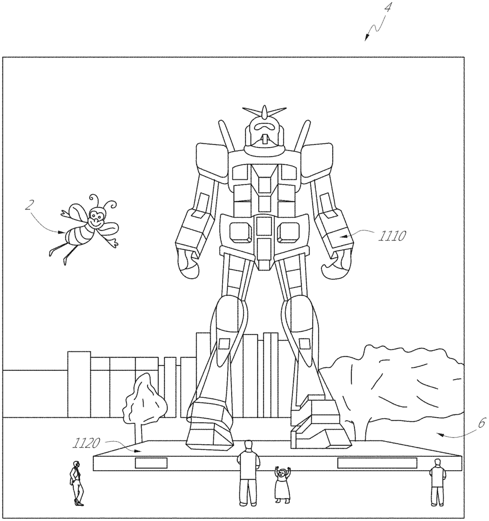
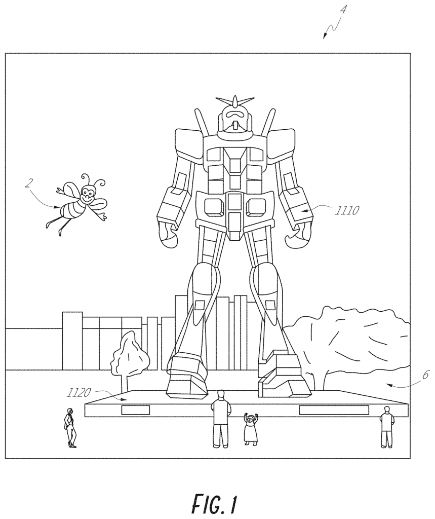
In FIG. In Figure 1, an augmented-reality scene (4) depicts a park-like environment (6) with people, trees, buildings and concrete platforms in the background. The user of AR technology perceives, in addition to these objects, that he also’sees’ a robot statue (1110) standing on the real-world platform (1120), and a cartoon-like avatar character (2) flying by which seems to be bumble bee personification. A robot statue (1110) standing on the real-world platform (11120), as well as a cartoon avatar character (2), which appears to personify a bumblebee, are all perceived by the user of the AR technology, even though they do not exist. “The human visual perception system can be very complex. It is difficult to create a VR/AR technology that allows for a natural, comfortable presentation of virtual images amongst real or virtual imagery.
Head mounted VR or AR displays are typically at least loosely attached to the user’s skull and move with their head movements. The data displayed can be adjusted to reflect the changes in the head position if the display system detects the head movements of the user. If a user with a head-worn device views a virtual representation on the display of a 3D object and then walks around that area, the 3D image can be re rendered for each view, giving the impression that the object occupies real space. The head-worn display can be used to show multiple objects in a virtual environment (for example, a rich virtual universe). Measurements of head pose, such as the position and orientation of the users head, can be used to re render the scene and give the user a greater sense of immersion.
In AR systems, the display system can render virtual objects in such a way that they appear to occupy space in the real-world in a way that makes sense for the user. Detecting the orientation and/or position of an object in real life, such as a handheld device, which is also known as a “totem”, can be useful. The display system can also present display information that is relevant to the AR system to the user. This allows the user interact efficiently with certain features of the AR system. The virtual objects can be rendered in a new way based on the head position of the user, so that they appear stable in relation to the real-world. For AR applications at least, the placement of virtual objects spatially in relation to physical objects can be a difficult problem. Placement of virtual objects within a view of a surrounding environment can be complicated by head movements. This is true regardless of whether the view captured is an image of ambient environment that is then projected or shown to the user or if the user directly perceives the view. A head movement may cause the field of view to change for the user, which would require updating the virtual objects displayed within the user’s field of view. Head movements can also occur in a wide range of speeds and ranges. The speed of head movement can vary, not only among different head movements but also within and across the ranges of one head movement. Head movement speed can increase initially (e.g. linearly or non-linearly) as a starting point and decrease when an ending point is achieved, with a maximum speed that lies somewhere between these two points. Rapid head movements can even exceed the capability of the display or projection technology in rendering images that are uniform and/or smooth motion for the end user.
Head tracking accuracy and latency, i.e. the elapsed period between the time the user moves their head and when the image is updated and shown to them has been a challenge for VR and AR. It is important that head tracking accuracy is high, and the system latency be low. This is especially true for systems that cover a large portion of a user’s field of vision with virtual elements. The system’s latency can cause a mismatch in the sensory systems of the user, which can result in motion sickness. “If the system latency increases, virtual objects’ apparent locations will be unstable when the user moves their head rapidly.

Other display systems may also benefit from accurate head pose detection. This includes head-tracked displays that are mounted on walls or other surfaces, and not worn by the user. The head-tracked displays act as a window into a scene. As a user moves their head in relation to the “window”, it is rendered. The scene is re-rendered according to the changing perspective of the user. Another system is a head worn projection system in which the display on a headset projects light onto real-world objects.
Also, to provide a realistic experience of augmented reality, AR systems can be designed to interact with the user. Multi-users can play a game of ball with a virtual object or ball. One user may ?catch? One user may?catch? In another embodiment, the first user is provided with a totem, such as a bat-like item communicatively connected to the AR system, to hit the virtual balls. In other embodiments a virtual interface can be shown to the AR user so that they can select from a variety of options. To interact with the system, the user can use totems or haptic devices. Wearable components may also be used.
Detecting the head position and orientation of the users, as well as detecting the physical location of real items in space allows the AR system display virtual content effectively and in a fun way. These capabilities may be difficult to attain, despite their advantages for an AR system. The AR system is able to recognize the physical location of an object (e.g. user’s hands, totems, wearable components, haptic devices, etc.). The AR system can correlate the coordinates of a real object with virtual coordinates that correspond to one or several virtual objects displayed to the user. It is necessary to use highly accurate sensors, and sensor recognition systems which track the position and orientation of multiple objects rapidly. Localization may not be performed at a satisfactory rate or with the precision required. There is a need to improve localization in the context AR and VR devices.
Examples of AR and VR Systems, Components and Systems
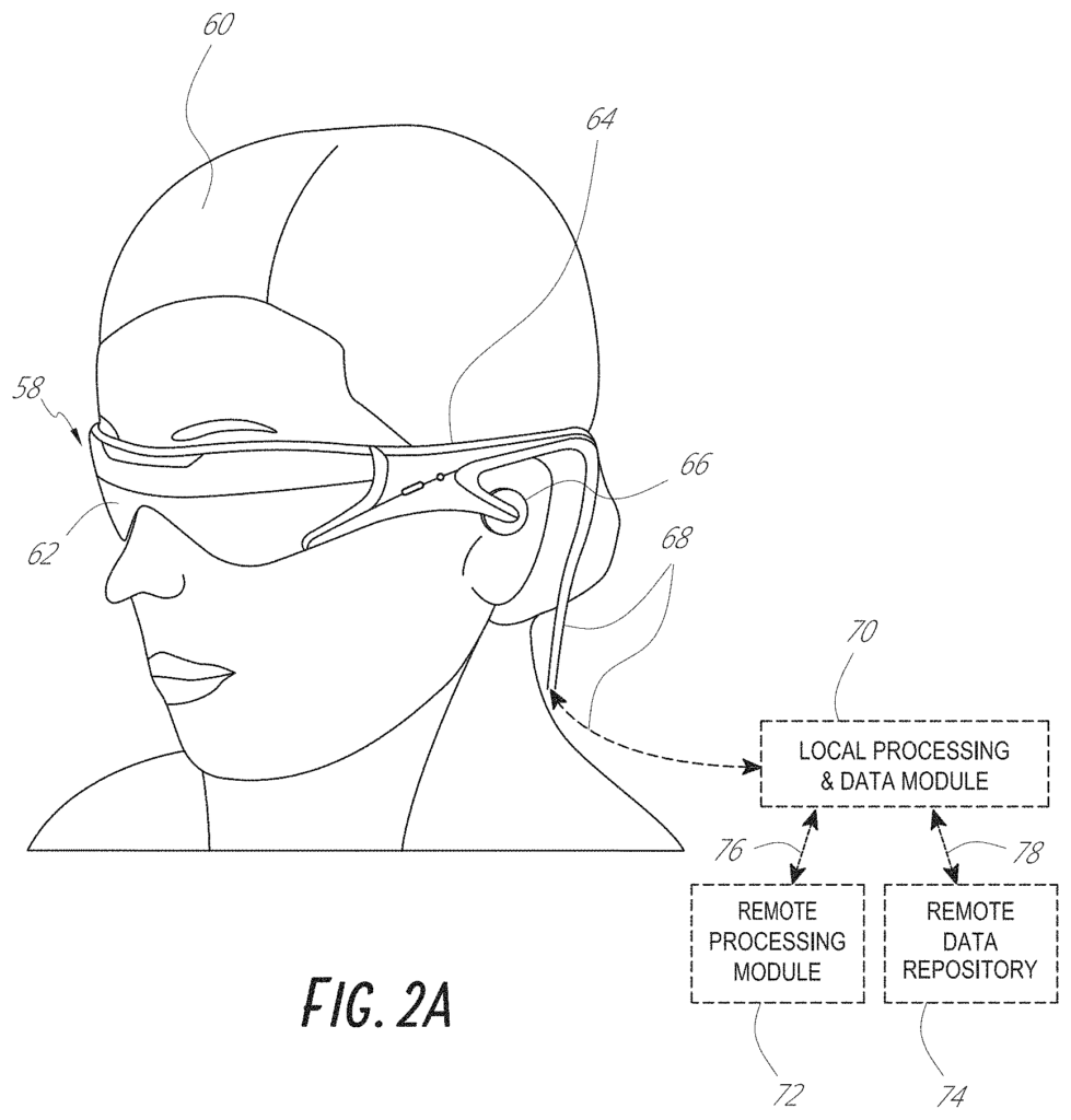
Referring to FIGS. Some general components options are shown in FIGS. The sections of the detailed description that follow the discussion of FIGS. 2A-2D, various systems, subsystems, and components are presented for addressing the objectives of providing a high-quality, comfortably-perceived display system for human VR and/or AR.
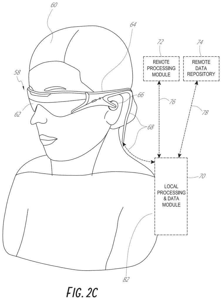
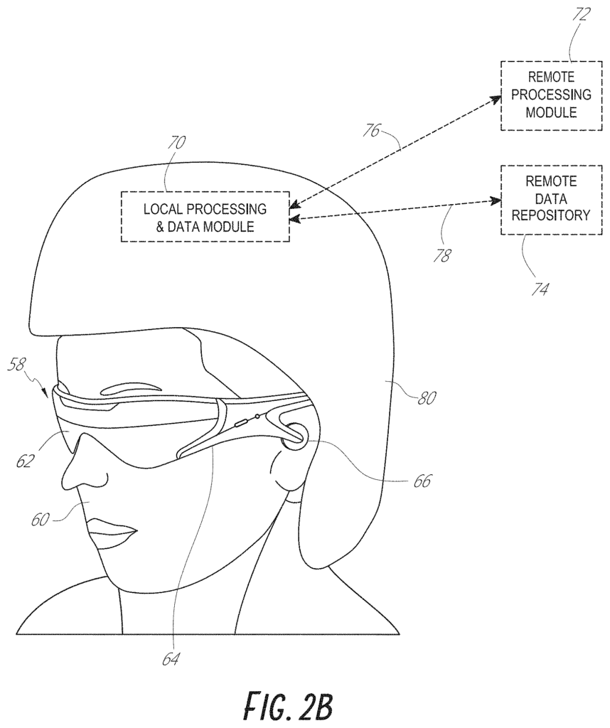
As shown in FIG. In 2A, a user of an AR system (60) wearing a head-mounted component (58) with a frame structure (64) coupled to a display (62) placed in front of their eyes is shown. In the configuration depicted, a speaker (66), coupled to the frame (64), is located adjacent to the user’s ear canal (in another embodiment, a second speaker, not illustrated, is placed adjacent to the other user’s ear canal to provide stereo/shapeable audio control). The display (62), which can be fixedly mounted to the frame (64) or fixedly mounted to a hat or helmet (80), as shown in FIG. The display (62) is operatively coupled (68), such as by a wired lead or wireless connectivity, to a local processing and data module (70) which may be mounted in a variety of configurations, such as fixedly attached to the frame (64), fixedly attached on hats or helmets (81) as shown in FIG. The embodiments of FIGS. 2C and 2D show headphones that can be removed from the torso (82) of the user (62) in a backpack-style configuration. 2D.
The local processing and data modules (70) can be connected (76, 78) to remote processing module (72) or remote data repository (74) via wired or wireless communication links. This allows the local processing and data modules (70) to be used to process, cache, and store data that has been acquired or processed by the remote processing module (72), and/or the remote data repository. Local processing and data modules (70) can be connected (76,78) to remote processing module (72) or remote data repository (74), for example via wired or wireless communications links. This allows the remote modules (72, 74) to be available to the local module (70).
In one embodiment, a remote processing module (72) can be composed of one or more powerful processors and controllers that are configured to process and analyze data or image information. In one embodiment, remote data repository (74) can be a large-scale digital storage facility that is accessible via the internet or another networking configuration. Resource configuration. In one embodiment, data and computation are stored in the local data and processing module. This allows for fully autonomous usage from any remote modules.
Referring to FIG. “With reference to FIG. As shown in Figure 3, a schematic illustrates coordination between the cloud computing assets (46) and local processing assets, which may reside in head mounted componentry (58) coupled to the user’s head (120), and a local processing module (70) coupled to the user’s belt (308; therefore, this component 70 can also be referred as a “belt pack” 3 . In one embodiment, cloud assets (46) such as server systems (110), are operatively connected (115) via wired or WiFi networking (wireless is preferred for mobility while wired is preferred for high-bandwidth data transfers or for high-data volume transfers) directly to (40 and 42) local computing assets such as processor and memories configurations coupled to the head (120) of the user and the belt (308), as described above. The computing assets that are local to the user can also be connected via wired or wireless connectivity configurations (44) such as the wired connection (68) described below with reference to FIG. 8 . In one embodiment, in order to maintain a small and low-inertia subsystem mounted on the user’s forehead (120), the primary data transfer between the user (46) and the cloud (46) can be through the link between a subsystem mounted on the belt (308), and the cloud. The head-mounted (120) system is primarily data-tethered with the belt-based subsystem (308) using wireless connectivity such as ultra wideband (?UWB?) Wireless connectivity such as ultra-wideband (?UWB?) is used to tether the head mounted subsystem (128) to the belt-based (308) subsystem.
A user can display information using a display device that is appropriate for the user. This could be a user interface, or a user display system, as shown in FIG. The user can transfer or “pass” aspects of a world relevant to their current real or virtual location. The user can be updated efficiently and effectively by transferring or?passing? A map of the globe may be continuously updated in a storage area that may reside partially on the AR system of the user and partially in cloud resources. The map is also referred to as “a passable world model?” It may consist of a large database containing raster images, 2-D and 3-D points, parameter information, and other data about the real-world. AR users are constantly capturing information about their environment, e.g. through sensors, cameras, IMUs etc. The map gets more accurate and complete.

With the configuration described above, a world model can be stored on cloud computing resources, and distributed from there. This world can then be ‘passable’. It is preferable to send a low-bandwidth version of the world to one or several users than to try to transmit real-time video or similar data. As shown in FIG. The cloud-based model of the world can be used to inform the augmented experience for the person standing near the statue (e.g., as shown in FIG. The cloud can be accessed by a person using a remote display, such as a computer on a desk. This information is then displayed on the display. A person who is physically present in the park can invite a friend to join them on a virtual and augmented-reality walk. The system must know the location of the street, trees, and statue.