
Invented by Kalon Ross Gutierrez, John Duncan, Douglas Griffin, Richard Schulze, Fanx Inc
The Fanx Inc invention works as follows
The method of enhancing a virtual reality experience (VR) includes: creating VR representations that are preprogrammed with virtual objects, associating them with stage kits, which each have a modular set and accessories, and marking the modular set to facilitate assembly; building one of these kits by: attaching the accessories according to one of the kit by using the coordinates indicated by the stage markings. Configuring a motion tracking to track the movements of a VR participant and one or more stage accessories and communicating this information to a The virtual objects’ locations and orientations correspond to the kit-specific stage accessories. The VR representations use tracking information from the motion tracking system in order to display imagery of VR objects while the VR participant moves around the stage accessories.

Background for Method to augment a virtual-reality experience
Field of Invention
This invention is a general description of virtual reality attractions and, more specifically, virtual reality attractions which combine physical elements with VR images.
Below are “Exemplary” and “illustrative” embodiments of the invention. For clarity’s sake, not all aspects of an actual implementation will be described here. Those skilled in the art know that many implementation-specific decisions must be made in order to achieve certain goals. It will also be understood that while such a project might be time-consuming and complex, it would be routine for someone with ordinary skill in this field who has the benefit of the disclosure. The skilled person will recognize that the preferred embodiment can be modified in many ways, and the principles described herein are applicable to any other embodiment. The present invention does not intend to be limited to any of the embodiments described and shown herein. Instead, it is intended to have the broadest scope possible consistent with the principles disclosed and the novel features.
The present invention is now described in relation to the figures attached. The drawings show various structures, systems and devices in a schematic manner for the sole purpose of explaining the invention and to avoid obscuring it with details well-known to those in the know. The drawings attached are used to illustrate and explain the invention. The words and expressions used in this document should be understood to have the same meaning as those who are skilled in the relevant field. Consistent use of a phrase or term herein is not intended to imply a special definition (i.e. a meaning that differs from the ordinary and common understanding of those skilled in this art). If a term or a phrase is to be given a different meaning than what skilled artisans understand, this will be stated in the specification.
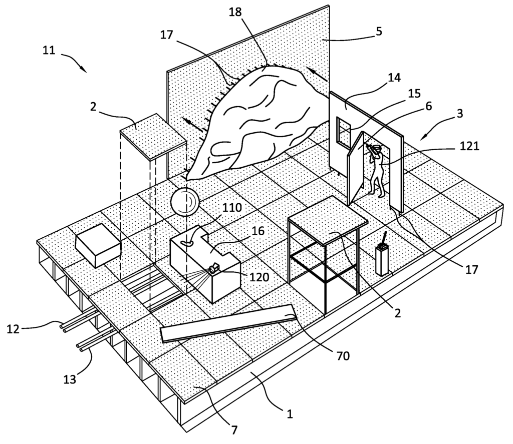
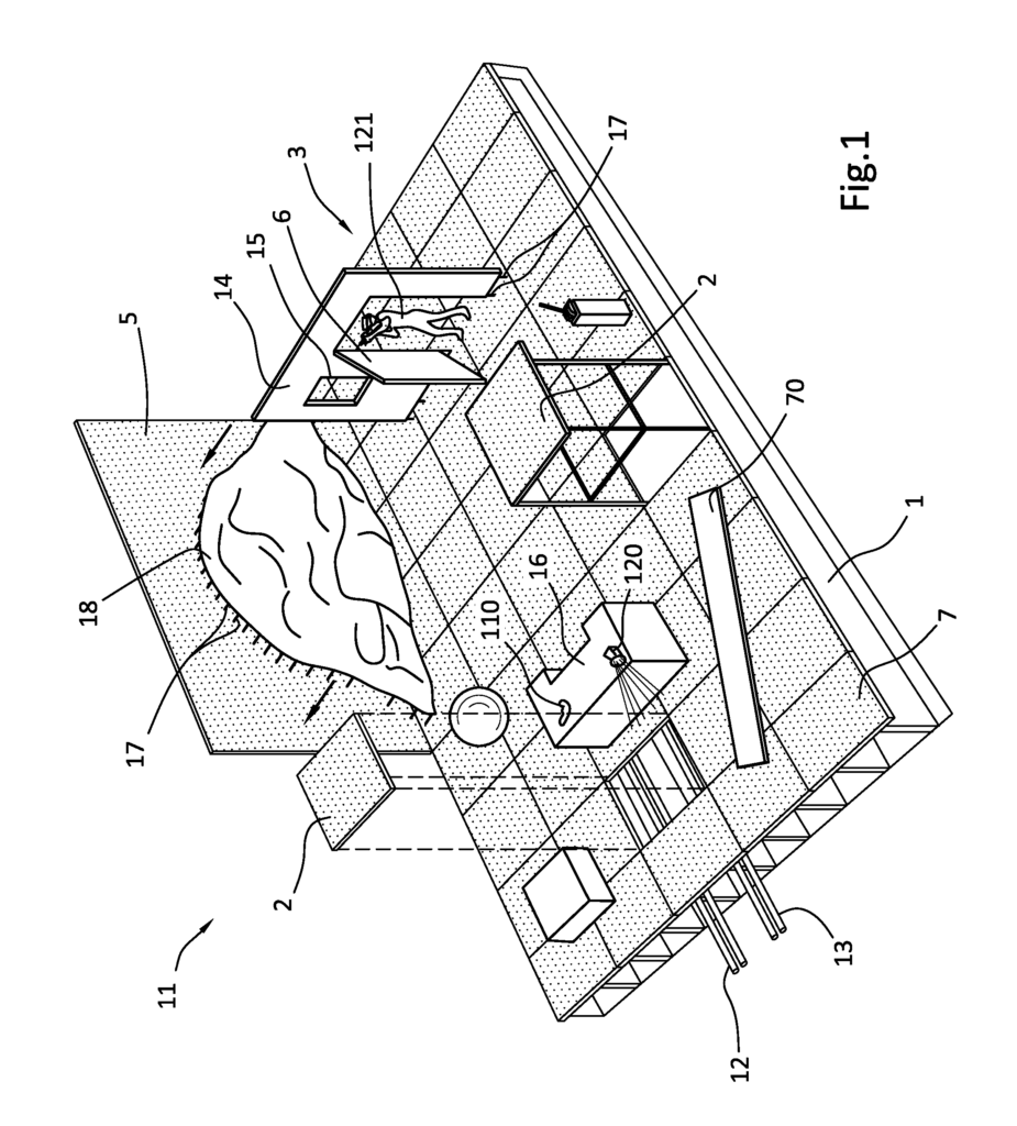
A modular stage 1 is made up of a number of modular stage sections 2, which are designed to be able to easily fit together and work in harmony to create the stage. The modular stage 1, along with its kit 11, of stage accessories 14,16,18,70,110,120, can be configured to fit a discrete space, such as 10 meters by 20 metres and 15 meters squared, that might be found at a mall or theater. The modular stage 1 and its kit 11 of stage accessories 14, 16, 18 70, 110,120 can be configured to fill discrete spatial areas, such as 10 meters by 20 meters or 15 metres by 15 meters, that might be found in a mall, theater, or other retail space.
In one embodiment, the modular stages 1 is a kit of a stage that can be purchased commercially (not to confuse with the accessory kit described herein). The stage 1 may include or be provided with discretely located (and preferably regular spaced) accessory mountings 7. The stage 1 may be elevated from the ground in one embodiment. This allows the signal lines 12 and the power lines 13 (e.g. the peg holes 7 on the platform 3) to pass under the platform 3, and through the openings of the platform 3 to service the accessories 14, 16 and 18, 70, and 110, and 120 mounted on stage 1.
The accessory mounts 7 can be placed in a grid pattern at pre-selected locations to accurately and conveniently represent discrete mounting places in a VR environment for stage accessories 14,16,18,70,110,120. In one embodiment, the accessory mounting 7 is a series of peg holes which are spaced regularly and are configured to receive accessories with cooperating pegs. The term “peg” is used in this application. The term “peg” is used to refer to both large and small structures. The peg hole 7 can be square, round, sized to accept a dimensional panel, or any other shape. The peg hole 7 is defined by an outer structure which, when combined with cooperating mountings 17 (e.g. pegs), provides sufficient strength to secure and stabilize any mounted accessories 14, 16, 18,70,110,120. In an alternative embodiment the stage platform 3 can be modified to include pegs 17, which are used for accessories 14, 16, 18 70, 110 and 120 that have cooperating holes 7.
The scope of this invention includes any suitable alternative to a peg and hole system, such as mounts that are in the form or seats, sockets interconnectors fasteners couplers couplings clamps hand-operated quick release clasps ties pins snaps links etc. The invention includes all female and male parts which attach an object to another.
Collectively the pegholes or other accessory mountings 7 of modular stage platform 3 align within rectilinear columns and rows, forming a regular pattern or grid 8. In one embodiment, each modular square 2 is identified by a set of primary alphanumeric marks 9. This grid density is used in the embodiment of a square 1 meter x 1 meter to provide a resolution of 1 meter x 1 meter. Each square or alternately dimensioned section 2 of the platform may be marked with its own set of secondary alphanumeric marks 9, in order to identify each accessory mounting 7 within the square or section. This grid density, in the 100-holes-per square embodiment provides a resolution of 1 decimeter by 1 decimeter. “The invention is not limited to square dimensions or grid density.
The positioning grid 8 is used to assemble the accessories 14,16,18,70,110,120 on the modular stage platform 3. As noted above, certain accessories (such as pegs), 14, 16, 18, 70 and 110 are mounted to the modular platform 3 using fittings 17. The accessory mounts 7, in conjunction with the fittings 17, secure the accessories 14, 18, 70,110,120 to the modular stage platform 3. The virtual reality objects can be aligned quickly and easily with the platform 3 using the accessory mounts 7.
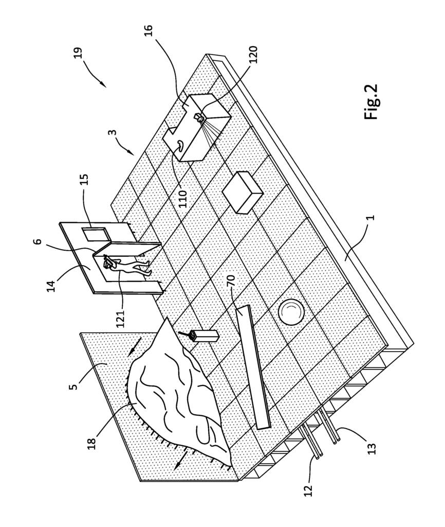

FIG. This ease of assembly and deconstruction is illustrated in 4 by a wall section 5, equipped with fittings 17, in the form pegs, positioned above peg holes 7, in a portion the modular stage platform 3 It may be easy to assemble the wall section 5. Simply identify the correct holes in the grid 8 by using the alphanumeric marks 9 that label the grid 8, then insert the pegs 7 into the holes. It may be easy to disassemble the wall section 5. All it takes is lifting it off the stage 3. You may choose to use quick-release connectors or clamps, e.g. clamps and connectors without tools, as they will only add a modest amount of time to the assembly and disassembly process.
Parts can be added or removed from the kit to create new configurations. In one embodiment, modular stage 1 has perimeter walls 5, which are also covered with a labeled pattern 8 to facilitate fastening objects in precisely, discretely, exactly, and vertically aligned locations. “A primary modular stage accessory, such as an interior panel, can include its own labeled pattern and grid of accessory mounts.
The grid-based method described above is preferred to other approaches for aligning a virtual construction with a physical structure. A common alternative is to build a permanent “one-up” A VR attraction which has not been modularly designed. Such attractions are not easily updated, which limits their ability to attract and retain repeat customers. A second approach would use video sensors or other sensors to determine the position and orientation of each fixed and stationary modular stage accessory 14. 16, 18. In practice, this approach would be less accurate or reliable than the invention’s method of aligning virtual and physical realms. This is because the VR objects and the physical world would be positioned in predetermined grid points or coordinates that select accessory mounts 7 already prepositioned. A second alternative is to arrange accessories 14, 16, 18 70, 110, and 120 on the stage platform 3, at predetermined coordinates, without the use of a grid 8, or any pattern of holes. This approach has the disadvantage that assembling the stage takes longer and is more error-prone. This approach has the disadvantage that stage builders cannot assemble stages as quickly and accurately as they can with a grid-based method. This may result in the virtual and physical worlds not aligning as precisely as with the grid-based method.
The stage 1 can be elevated to the level of the ground in one embodiment. This allows the signal lines 12 to run underneath the platform 3, and the power lines to pass through the openings on the platform (e.g. the peg holes 7).
Click here to view the patent on Google Patents.