Invented by Robert E. Ralston, Justin D. Bloom, Novatel Wireless Inc, Feeney Wireless LLC
The Novatel Wireless Inc, Feeney Wireless LLC invention works as follows
The invention’s embedded devices provide an intelligent routing vehicle enhancement system and method. Intelligent land buoys are able to be placed close to roads. Intelligent land buoys are able to gather information about roadways and the vehicles that travel thereon. The situational awareness information can be compressed by the intelligent land buoys. Remote computer servers can decompress the situational awareness information received from the plurality intelligent land buoys and then process it. One or more remote computers can generate vehicle operational information information using at least the compressed situational awareness information. They can also transmit this information to the plurality intelligent land buoys or directly to one or two autonomous or semi-autonomous vehicle.

Background for Dynamic routing intelligent vehicle enhancement system
Conventionally, vehicles were operated by humans. Recent advances have made it possible for vehicles to be autonomous, or at least semi-autonomous. Safety can be improved by eliminating human error which is the main cause of accidents. The current methods are limited by the lack of detailed information, such as the line of sight, road obstructions, misinterpretation and misalignment of localized data (e.g. mistaking a pedestrian with a stationary object) that is available to the vehicle. Because autonomous vehicles often have to make life-or-death decisions for humans, this limited information is a challenge. It is also insufficient to provide a safety standard acceptable to the public and government.
In order for advanced autonomous vehicle technology in the world to become mainstream, safety improvements must be made. Automated systems may be reliable for some or all of the time. However, humans might need to intervene in the event that the system fails, especially in adverse weather conditions or unexpected events. A human may be required to control the vehicle in unusual situations, for example, within a specified time period, such as 10 seconds or 20 seconds. Governments may mandate such requirements to maintain safety and quality in the system. The problem is that the technology currently in use does not provide sufficient information to enable alerts under these conditions. As a result, it fails achieve adequate levels of safety.
Conventional navigation technologies do not provide enough granular information to enable autonomous vehicles to operate at high levels of safety, performance and efficiency. Traffic conditions are often dynamic and change frequently. Traffic jams can happen at any hour of the day. An accident can cause temporary chaos. Road obstructions can pose danger. Roadways are not efficiently used. Drivers take certain routes when there are better routes. The undesirable results include congestion, frustration, roadrage, fuel inefficiencies, and other unpleasant consequences.
Accordingly, there is still a need for a dynamic routing intelligent car enhancement system and other related methods. Smart grids are also needed to increase the utility and capacity on existing roads. These limitations are addressed by the embodiments of the invention.
Reference will now take place in detail to various embodiments of the inventive idea, which are illustrated in these accompanying drawings. These drawings may not be drawn to scale. The following description will provide a detailed explanation of the inventive concept. However, it should be noted that even those with ordinary skill in the arts can practice the inventive idea without needing to know these details. Other cases, well-known procedures, components, circuits and networks are not described in detail to avoid confusing aspects of the embodiments.
It will be clear that although the terms first, third, and so on. These terms may be used to describe different elements. However, they should not be limited. These terms can only be used to differentiate one element from the other. A first network could be called a second network. A second network could also be called a first networking, but this is not outside the scope of the inventive idea.
It will be clear that an element or layer is called?on? when it is connected to another. ?coupled to? ?coupled to? Another element or layer can be connected or coupled to it. Intermediaries elements and layers may also be present. An element that is “directly on” can be referred to as such. ?directly connected to? ?directly related to? a layer or element, and there are no other elements or layers. Like numbers are used throughout to refer to like elements. The term “and/or” is used herein. The term?and/or? refers to any combination of one or more of these listed items.
The description of the inventive idea herein uses terminology that is intended to describe particular embodiments and not limit the scope of the invention. The singular forms?a,?an and?the are used in the description and appended claims. The singular forms?a?,?an?? sowie?the? are used in the description of the inventive concept and the appended claims. Unless the context indicates otherwise, they are meant to be inclusive of plural forms. Also, it will be clear that the term “and/or” is used herein. It will also be understood that the term?and/or? as used herein refers and encompasses all combinations of any or all of the listed items. Further, the terms “comprises” and/or “comprising” are used interchangeably. and/or ?comprising,? When used in this specification, they indicate the presence of the stated features, integers and steps, operations and elements and/or their components. However, it does not preclude the addition or presence of other features, integers and steps, operations and elements and/or groups thereof.
FIG. “FIG.
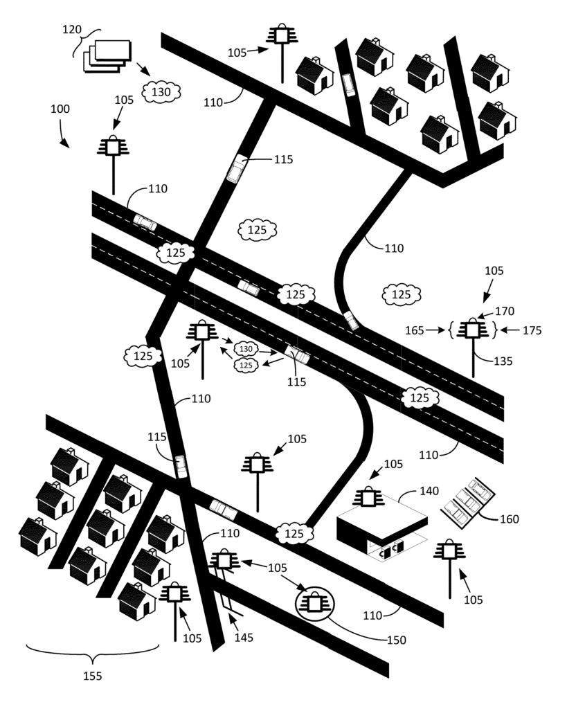
Intelligent Land Buoys (e.g. 105) can be proximately located to a plurality road (e.g. 110). “Roadways” is a broad term. Roadways can refer to roads, intersections and bridges as well as railways, railway crossings and the like. Each intelligent land buoy 105 can collect situational awareness information (e.g. 125) about one or several route segments 110 and one or more vehicles (e.g. 115) travelling thereon. The intelligent land buoys can be connected to one or more vehicles 115 to receive situational awareness information (125). Situational awareness information (125) can contain information about the current state of reality in relation to adjacent areas and vehicles, as well as information about vehicle route segments. Below are detailed descriptions of situational awareness information (125).

The intelligent landing buoys 105 are capable of compressing and/or storing the situational awareness data 125. The compression method is further explained below. Remote computer servers, such as 120, can be communicatively connected to the intelligent buoys 105. They can then receive the compressed situational information 125 from the plurality intelligent land buoys. Remote computer servers 120 can be distributed or clustered. One or more remote computers servers 120 can compress the situational information 125, process it 125 and/or store it 125. The remote computers 120 can therefore generate vehicle operational intelligence information 130, based at most on the decompressed conditional awareness information 125. This is also described in detail below.
One or more remote computers 120 can transmit vehicle operational intelligence information 130 the plurality intelligent land buoys105. One or more intelligent land buoys (105) may transmit operational intelligence information 130 to one or more vehicles (115). Alternately, remote computers 120 can transmit vehicle operational intelligence information 130 directly to one or more vehicles. This means that a vehicle’s map service or navigation device can receive operational intelligence information 130 to enable it to access real-time, highly accurate operational information.
The intelligent land buoys (105) can be set up to transmit a beacon that includes vehicle operational intelligence information 130 to one or more vehicles 115. The beacon can be transmitted periodically. The beacon can also be transmitted continuously. A plurality of intelligent landing buoys 105 may be placed at an elevation higher than the tops of one or more of the vehicles 115. They can transmit the beacon, including vehicle operational intelligence information 130, to the vehicles 115. Each of the intelligent buoys 105 may be attached to a utility pole 135, traffic signal apparatus 145, building 140, hovering drone 150, or radio tower (not illustrated).
The vehicle 115 may include an autonomous vehicle or semi-autonomous vehicle. A vehicle may be used to transport people primarily. The vehicle can also be used to transport goods, people, or a combination of both. The vehicle could be, for example, a car, truck, train or other suitable type of vehicle. Artificial intelligence is used to create autonomous vehicles. An autonomous vehicle, for example, can navigate and operate itself without the assistance of a human operator. Semi-autonomous vehicles also include artificial intelligence, but it is not as powerful as an autonomous vehicle. A semi-autonomous vehicle might require assistance from humans to operate. This disclosure refers to a “vehicle”. Or?vehicles? Such vehicle(s) can be either autonomous, semi-autonomous or any combination thereof.
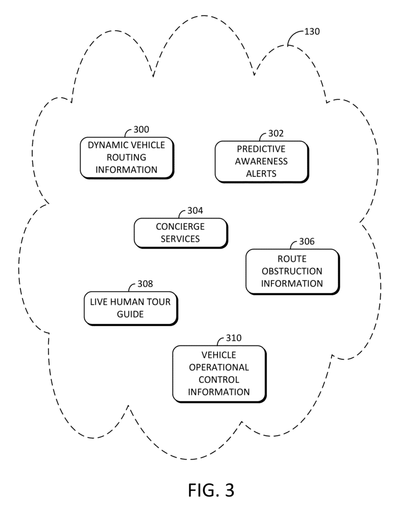
The vehicle operational information 130 can contain dynamic vehicle routing information. The vehicle operational intelligence 130, for example, can help a vehicle navigate from one geographic location to another. These geographic locations could be located in the neighborhood 155, in a garage 160, close to a building 140 or on a highway like 110. The vehicle operational intelligence 130 may also include a predictive alert that indicates a time frame within which an occupant of a vehicle is advised to assume operational control.
Each intelligent land buoy 105 can have one or more short-range radio transceivers (165) to receive from the one/more vehicles 115 at least a portion of the situational information 125 about roadways 110 and vehicles 115 that travel thereon. Each of the intelligent land buoys (105) can also include one or two visible light cameras (e.g. 170), to receive at most a second part of the situational information 125 about roadways 110 and vehicles 115 that travel thereon. Each of the intelligent land buoys (105) can also include one or several long-range radio transceivers (175) to transmit to remote computers 120 the compressed situational information 125. Below are additional details about the various components of intelligent land buoys (105).
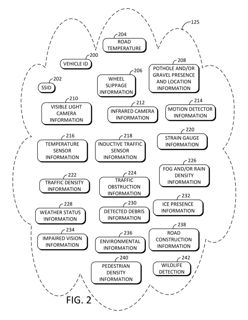
FIG. 2. illustrates a diagram showing the example of situational awareness information (125) (of FIG. 1), collected by the intelligent land buoys (105 (of FIG. 1. According to different embodiments. Situational awareness information (125) can include, for instance, a vehicle identification 200, a service sets identification (SSID 202), road temperature 204 and wheel slippage information 206, motion detector information 218, temperature sensor information 218, inductive traffic sensor info 218 and strain gauge information 220. Traffic density information (222), traffic obstruction information 226, fog and/or rainfall density information 226, weather status data 228, detected debris information (230), ice presence information (232), environmental information 236, road/tunne detection information 238, maintenance information 238, or construction information 238, or road or tunnel construction information 238, or maintenance information 238, and road or road or road construction or repair information 238, and maintenance information 238, and road or road or road or tunnel construction information 238, and maintenance information 238, and road or road or road or road information 238, or road or road information 238, or road or road or road or road or road information 238, or road or 240, or 240, or wild life information 242, and road information 236, or road or tunnel construction information 238, or 235, or 232, or 240, or ad information 236, or 124, or 232, or 243, or 240, or a 238, or 230, or a 238, or maintenance information 236, or road information 238, or 238, or s 240, or a, or a 242, or 123, or 240, or 125, or a, or a, or a, or a, or a, or 62, or z, or, or, or, or, or, or the like.
An example: One or more intelligent land buoys 105 can detect a vehicle associated to a specific SSID among the one-or more vehicles 115 and a second vehicle associated with that particular SSID among the one/more vehicles 115. This allows for the determination of its location, speed, distance traveled, etc.
In addition, or alternatively the intelligent land buoys105 can transmit both the first and second location information to one or more remote computers servers 120 (see FIG. 1), and one or more remote computers servers 120 can determine the exact location, distance traveled and speed of the vehicle based at minimum on the first and second location information.
The intelligent land buoys (105) can compress, store, or transmit the gathered situational information 125 to one or more remote servers 120 (of FIG. 1). Below are the types of compression. One or more remote servers 120 are able to receive, decompress, process, and transmit the situation awareness information (125), and operational intelligence information (130) in real-time, or near real time to the intelligent land buoys (105)