Invented by Zhang Li, Jun Zhan, Yiqing YANG, Xuan Liu, Yu Cao, Siyang Yu, Guang Yang, Baidu USA LLC
The Baidu USA LLC invention works as follows
Described is a system and method for creating a driving scenario for an automated driving simulator. A camera attached to a vehicle may be used to capture real-life driving scenarios data. The system can then analyze the two-dimensional data to create a 3-D driving simulation. This analysis could include the detection of objects (e.g. vehicles, pedestrians, etc.) within the two-dimensional data. The object’s movements can be determined based on its position, trajectory, velocity, etc. The object’s information may be projected onto a map to be used in the generation of the three-dimensional driving simulation. Cost-effective cameras allow for the collection of large amounts of driving data. This may be used to cover all possible driving scenarios that an autonomous vehicle might encounter.

Background for Vision-based driving scenario generator to autonomous driving simulation
Driving simulations are used often to test different components of autonomous driving systems. Decision systems) that could be used in an autonomous driving car. The simulation’s quality is directly related to the autonomy of the autonomous driving car. Simulators are often built using manual inputs that require extensive configuration. However, simulations that are manually configured can often not reflect the real-life driving situations. Complex data may also be collected from an autonomous driving car. It is difficult to collect this information as it requires a fleet autonomous driving vehicles to capture all possible driving scenarios a vehicle might encounter. There is an ongoing need to improve the driving scenarios that autonomous driving simulations can be used for.
Various embodiments and aspects will be described using details discussed below. The accompanying drawings will illustrate these various embodiments. These descriptions and drawings do not limit the disclosure. To provide an in-depth understanding of different embodiments of this disclosure, many details are provided. In some cases, however, the details of well-known or common details are not discussed in order to give a concise discussion about embodiments of this disclosure.
Refer in the specification to?one? embodiment? or ?an embodiment? This means that at least one embodiment can include a specific feature, structure, or characteristic described with the embodiment. “Embodiment” may appear in different places in the specification. The phrase “embodiment” appears in different places in the specification, but they do not always refer to the same embodiment.
Described is a system and method for creating a driving scenario to drive an autonomous driving simulator. Images captured by cameras attached to vehicles may be used to generate the driving scenario data. Cost-effective cameras allow for the capture of large amounts of driving data. This may be used to cover all possible driving scenarios that an autonomous vehicle might encounter.
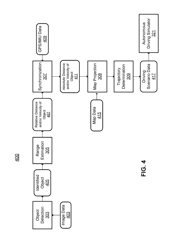
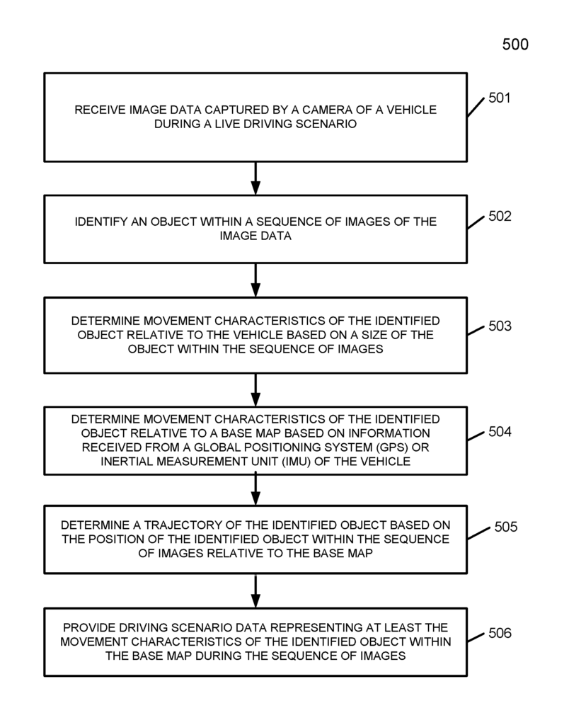
In one embodiment, a driving simulation may use driving scenario data (e.g. High definition map) to create driving simulations. Two-dimensional data such as images from a camera may be used to generate driving scenario data. The system may use two-dimensional image data (e.g., from a camera) to generate driving scenario data. This is a cost-effective way to get real-life driving situations. The system can analyze captured image data (e.g. video) and identify objects (e.g. vehicles, pedestrians, etc.) The two-dimensional data can be used to determine the object’s movement characteristics, such as its position and velocity. The system could determine the movement characteristics of an object identified by measuring its size in a sequence of images (e.g. A set of frames. Additional information about the position and velocity of an image-capturing vehicle can be used to determine absolute values or relative values of the object’s movement characteristics.
For instance, GPS location information and inertia information may be provided by sensors on the vehicle that captures images. These information can be synchronized with captured image data. An absolute position, e.g. Based on GPS location information, an absolute position (e.g. This information can be used to extrapolate the absolute position of an object. The driving simulator can then use the driving scenario data that includes the object’s determined movement characteristics. The driving scenario data could include information about the type of object, its velocity, position, trajectory, and other details. This driving scenario data can be used to project the object onto a map base to create a three-dimensional driving simulation. You can use the driving simulator to test various components of autonomous driving systems. The driving scenario data can be used, for example, to test various components or modules of an autonomous driving program.
The system allows for the verisimilitude and simulation of a wide range of driving scenarios, while keeping costs down. The generated simulations could be an important component in improving the safety and performance of autonomous driving systems. Referring to FIGS. The system may also include an image-capturing vehicle that captures real driving data, which is then used by a simulation generation system to generate driving scenarios data. The system can analyze two-dimensional images to generate three-dimensional driving simulation data, as explained.
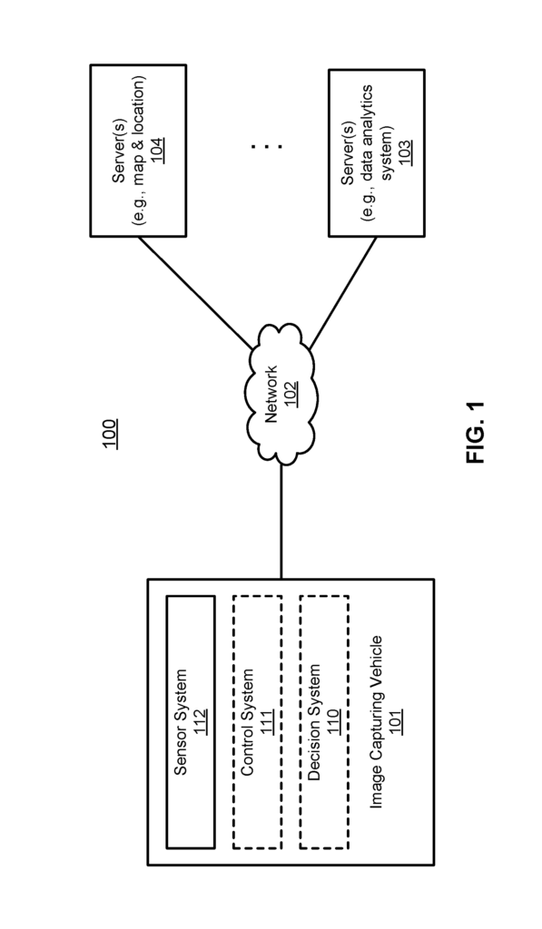
FIG. “FIG. An autonomous driving vehicle or non-autonomous vehicle may be included in the image capturing device 101. a camera, GPS unit, IMU unit, etc.). The driving scenario data can be generated from image data taken by a more cost-effective camera, as opposed to expensive LIDAR equipment. However, the image data can be drawn from any vehicle. In one embodiment, the driving simulator generating system may receive image data from an off-board camera of a vehicle that is not autonomous. This may also include crowd-sourced data from multiple vehicles/users, to provide a greater amount of driving scenario data that can be used to generate driving simulations. Referring to FIG. Referring to FIG. 1, the system 100 comprises an image-capturing vehicle 101, which can be communicatively connected to one or more servers (103-104) over a network of 102. Multiple autonomous vehicles may be connected to one another and/or to servers 103-104 via network 102.
An autonomous driving vehicle is a vehicle that can be set up in an autonomous mode, where it navigates in a given environment without any input from the driver. An autonomous vehicle may include a sensor system that detects information about the environment. The vehicle and the controller(s) associated with it use the information to navigate the environment. In one embodiment, image-capturing vehicle 101 may operate in manual mode, full autonomous mode or partial autonomy.
In one embodiment, the image capturing vehicle 101 may optionally include (e.g. If the image capturing device 101 is autonomous driving, it may include a decision systems 110 and vehicle control system 112. The image capturing device 101 may also include common components found in other vehicles such as an engine, wheels and steering wheel. These components can be controlled by vehicle controller system 111 or decision system 110 using a variety communication signals and/or commands such as acceleration signals, commands, deceleration signal or commands and steering signals or orders, braking signals, or commands.

Components 110-112 can be communicatively connected to one another via an interconnect or bus, a network, and/or a combination thereof. Components 110-112 could be communicatively connected to one another via a controller-area network (CAN) bus. A vehicle bus standard, the CAN bus, allows microcontrollers and devices communicate with one another in applications that do not require a host computer. It may contain a message-based protocol that was originally designed for multiplex wiring in automobiles but can also be used in other contexts.
Network 102 can be any type or network such as a local network (LAN), a large area network (WAN), or a combination of wired and wireless networks. Servers 103-104 could be any type of server or cluster of servers such as Web, cloud, application servers, backend or combination servers. Servers 103 to104 could be data analytics servers or content servers, traffic information server, location servers, map and points of interest (MPOI), severs, or other types.
Server 104 may contain map and location information which can be used to process the image data described further herein. One embodiment of the server 104 could provide traffic data that can be used in a simulation. Server 103 could be used to provide data analytics services to a range of clients. One embodiment of server 103 may contain driving statistics, including information about driving commands (e.g. throttle, brake, steering commands) and vehicle responses (e.g. speeds, accelerations or directions) that were captured by sensors at different times. Other information that may be included in driving statistics include information about the driving environment at different points in times, such as routes (including starting/destination locations), MPOIs and road conditions. These additional details may be input to the simulation-generating system.
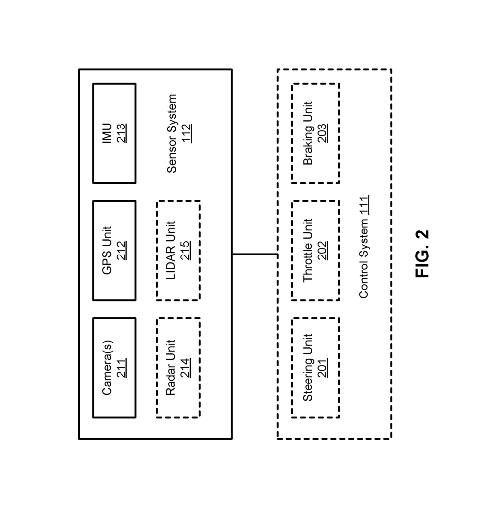
Referring to FIG. “Referring now to FIG. GPS system 212 could include a transceiver that provides information about the vehicle’s position 101. One or more cameras 211 could capture images of the surrounding environment 101. Cameras 211 can be either still cameras or video cameras. The mechanical movement of a camera can be achieved by positioning it on a rotating or tilting platform. The IMU unit 213, which is based on inertial acceleration, may detect changes in the vehicle’s position and orientation. Optionally, the sensor 112 may (e.g. If the image-capturing vehicle 101 is an autonomous driving vehicle, it may include a radar unit (214) and/or LIDAR unit 215 Radar unit 214 could be a system that uses radio signals to detect objects in the local environment 101. Radar unit 214 can sense speed and/or direction of objects in some embodiments. LIDAR unit 215, which may detect objects in the environment where the vehicle 101 is located, can use lasers to locate them. LIDAR unit 215, among other components, could contain one or more laser sources and a laser scanner.
Sensor 112 may also include other sensors such as a sonar, infrared, steering, and audio sensors (e.g. microphone). An audio sensor can be used to record sound from the surrounding environment 101. An audio sensor can be used to detect the environment around the vehicle 101. A throttle sensor and brake sensor detect the vehicle’s throttle and braking positions, respectively. Sometimes, a throttle sensor or a brake sensor can be combined to form an integrated throttle/braking sensor.
In one embodiment, vehicle controller 111 may include throttle unit 200 (also known as an acceleration unit) and steering unit 201. The steering unit 201 adjusts the vehicle’s direction. Throttle unit 200 is used to control the speed or acceleration of the engine. Braking unit203 is responsible for deceleration of the vehicle through friction that slows the tires or wheels. The components shown in FIG. 2. may be implemented in hardware or software, or both.
When the image-capturing vehicle 101 is autonomous, certain or all of its functions may be controlled by decision system 110. This is especially true when the vehicle is in autonomous driving mode. Decision system 110 contains the hardware (e.g. processor(s), memory storage and software) required to receive data from sensor system 112, control systems 111. This information is used to process the information and plan a route from a starting point or point to a destination point. Then, the driver of vehicle 101 will be driven based on that planning and control information. Alternately, decision system 110 can be integrated with vehicle controller system 111.
While autonomous vehicle 101 is moving along a route, decision system 110 could also receive real-time traffic information via a traffic information server or system (TIS). Servers 103-104 can be managed by third parties. Alternately, servers 103 to 104 can be integrated with decision systems 110. Based on real-time traffic information and MPOI information as well as location information detected or sensed via sensor system 112, decision system 110 can plan the optimal route and drive vehicle 101 according to the route chosen to reach the destination safely and efficiently.
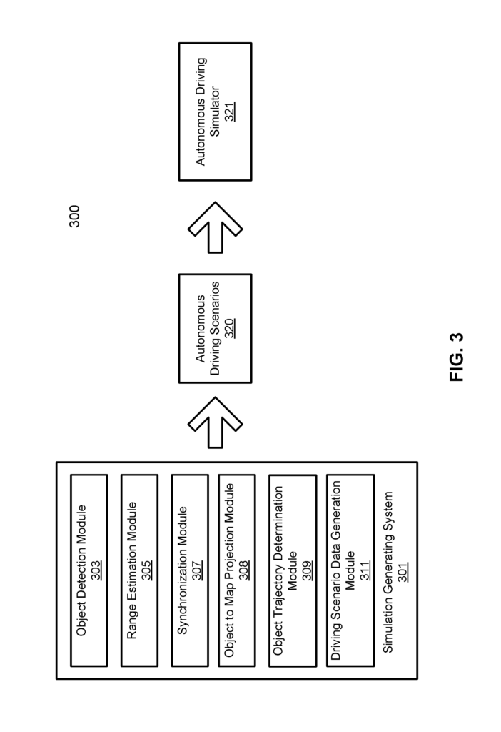
FIG. 3. This block diagram illustrates an example system 300 that can be used to generate an autonomous driving scenario according to one embodiment. Referring to FIG. 3. System 300 may also include a simulation-generating system 301. One embodiment of the simulation generating systems 301 may contain one or more modules (or components) that perform tasks (or procedures. Examples include object detection module, range estimation module, 305, synchronization, object to map projection, module 308, and object trajectory determination module 309. Driving scenario data generation module 311. These tasks can produce data that can be used to create driving scenarios 320.
Object detection module303 is designed to detect objects in image data. The detection can include the identification of any objects that might be relevant for autonomous driving vehicles. In one embodiment, objects could include other traffic entities, such as pedestrians, cyclists, and other autonomous or non-autonomous vehicles. Additionally, objects can also include non-traffic-related (e.g. Static objects, such as traffic control objects and obstructions (e.g. pylons, barriers, traffic signs, electronic signs, etc.). Processing image data may be part of the object detection process (e.g. video). One embodiment of object detection can be performed at the frame level, by treating the video sequence as a series of images. The detection could include the identification of objects within specific frames in the image data. Any suitable technique may be used to identify objects in the image data.

In one embodiment, object detection 303 could implement a machine-learning algorithm. A deep learning algorithm, such as Fast Region-based Convolutional Network (Fast RCN), may be used to detect objects. There may be various manipulations of the two-dimensional images data. The detection could include overlaying a boundary around an object to identify it. The boundary box for the object can be referenced in a series of images as part of the processing.