Invented by Venkataramanan Krishnaswamy, Richard J. Barth, JR., Keith D. Paulsen, Dartmouth College
Tissue resection is a surgical procedure that involves the removal of a portion of tissue from the body. This can be done for a variety of reasons, including the removal of cancerous or diseased tissue, the removal of excess tissue, or the removal of tissue for diagnostic purposes. Traditionally, tissue resection has been done using open surgery, which involves making a large incision in the body. However, advances in technology have led to the development of minimally invasive surgical techniques, which involve making smaller incisions and using specialized tools to perform the surgery.
One of the key challenges in minimally invasive surgery is the need for precise and accurate tissue removal. This is where systems and methods for guiding tissue resection come in. These systems and methods use advanced imaging technologies, such as MRI, CT, or ultrasound, to create a detailed map of the tissue that needs to be removed. This map is then used to guide the surgeon during the resection procedure, ensuring that only the targeted tissue is removed.
The market for systems and methods for guiding tissue resection is expected to continue to grow in the coming years. This growth will be driven by several factors, including the increasing demand for minimally invasive surgeries, the growing prevalence of cancer and other diseases that require tissue resection, and the development of new and more advanced imaging technologies.
One of the key players in this market is Intuitive Surgical, a company that specializes in robotic-assisted surgery. Intuitive Surgical’s da Vinci Surgical System is a robotic surgical system that is used to perform minimally invasive surgeries. The system uses advanced imaging technologies to create a detailed map of the tissue that needs to be removed, and then uses robotic arms to guide the surgical instruments during the resection procedure.
Other companies that are active in this market include Medtronic, Stryker, and Johnson & Johnson. These companies offer a range of systems and methods for guiding tissue resection, including advanced imaging technologies, surgical navigation systems, and robotic-assisted surgery systems.
In conclusion, the market for systems and methods for guiding tissue resection is a growing and important market in the healthcare industry. As the demand for minimally invasive surgeries continues to increase, the need for more precise and accurate tissue removal will become even more important. Companies that are able to develop innovative and effective systems and methods for guiding tissue resection will be well-positioned to succeed in this market.

The Dartmouth College invention works as follows
The method of guiding the resection local tissue of a patient involves generating an image of the patient and automatically determining multiple surgical guidance clues that indicate three-dimensional spatial characteristics associated with the tissue. It also includes visualizing the surgical cues in relation to the surface. The system for generating guidance cues to guide resection of local tissue from a person includes a location unit for processing the image of the patient in order to determine the three-dimensional properties of the tissue and a cue generator that generates the guidance cues using the three-dimensional properties. “A patient-specific locator for guiding the resection local tissue from a person includes a surface that matches the surface of a patient and features indicating various surgical guidance cues.
![]()
Background for Systems and Methods for Guiding Tissue Resection
Navigation technology is often used to assist in tissue removal surgery. This allows the surgeon to perform the procedure while guiding it. A biopsy can be guided using ultrasound imaging in order to make sure that it is done at the correct location. Similarly, the removal of an intervertebral disk from a spinal segment could be guided with fluoroscopic x ray guidance so as to not damage the spinal cord or the nerve roots. The accuracy of cancer-related tissue removal is usually very high. In order to diagnose cancer, a biopsy must be performed on tissue that is suspected of being cancerous. This means the sample should come from the tumor and not from normal tissues nearby. “Any cancerous tissue left behind after a surgical removal of a tumor can be harmful to the patient.
Traditionally, breast tumor removal is guided with a radio-opaque clips placed inside the tumor. Breast tumor resection involves the removal of only the cancerous tissue, rather than the entire breast. During a biopsy, the radio-opaque clips can be placed into the tumor. Imaging, such as ultrasound imaging, magnetic resonance imaging (MRI), and mammography, is used to guide the wire insertion. The removal of all filaments and fimbriae from the perimeter of the tumour is difficult. Breast tumor resections are often accompanied by radiation therapy to destroy any remaining cancerous tissue. About one-fourth of women who have undergone breast cancer resection will need to return in order to remove more cancerous tissue near or at the original site of resection.
In one embodiment, a technique for guiding the resection local tissue of a patient comprises generating an image, which includes both an image (of the local tissue) and an image (of at least a portion surface of the person). The method also includes automatically determining at least in part, based on the at least one picture, a plurality surgical guidance clues indicating spatial properties of three-dimensional local tissue and generating a visualisation of the surgical cues with respect to the surface.
In one embodiment, a method for generating surgical cues to guide resection of local tissue in a patient comprises a location module that processes at least one patient image to determine the three-dimensional properties of the tissue and a surgical-cue generator that generates the cues using the three-dimensional properties.
In one embodiment, the patient-specific location form includes a surface that is matched to the surface of a patient at the local tissue location. The patient-specific location form then fits the surface near the local tissue location. The patient-specific location form includes a plurality features that indicate a plurality surgical guidance cues.
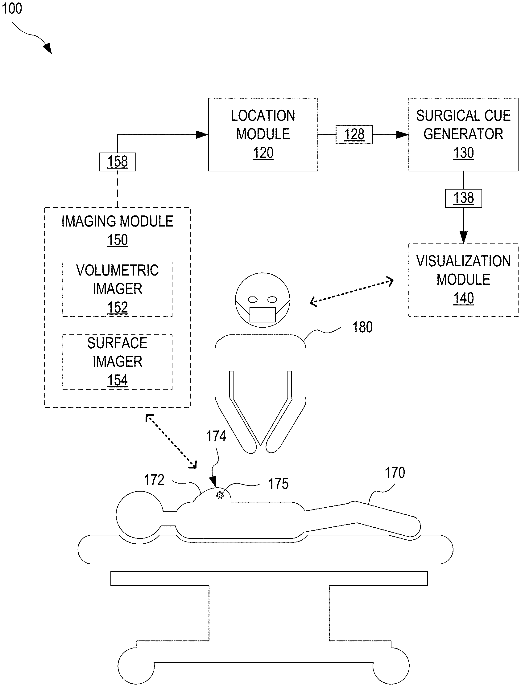
FIG. “FIG. 1 shows an exemplary system 100 that can be used to guide the resection of tumors 175 in a breast 172 from a patient 170- Resection surgery is done with the patient in a supine (backwards) position. Breast 172 will be facing up. System 100 uses supine images of breast 172 158 to determine geometrical characteristics of the resection to remove tumor 175 and generates surgical guidance cues to guide the resection. Herein, a ?supine image? Refers to an image showing patient 170 lying in the supine posture. Each supine 158 image is an image of breast 172, which corresponds to breast 172 being in the same position as the resection surgery. Supine image is taken while patient 170 in the supine or prone position. The surgical guidance cues (138) directly or indirectly indicate the three-dimensional (3D), spatial properties of tumor 175, in the supine positioning used during resection.
System 100 comprises a location module that processes at the very least one breast image 158 in supine to determine the 3D spatial properties of the tumor 175 The system 100 also includes a surgical guide generator 130 which determines surgical guide cues 138. The surgeon 180 performs resection surgery to remove a tumor 175 on the patient 170 using surgical guidance cues. Herein, a ?surgeon? “A surgeon” can refer to one, two, or more people, or one, two, or three computer systems, or one, or more robotic devices.
In one embodiment, system 200 further comprises a visualization module that displays surgical guidance cues for surgeon 180. In one example visualization module 140 displays the surgical guidance cues on a computer generated model of breast 172.
In one embodiment, the system 100 includes an image module 150 which captures at least one image 158 or alternatively, captures one or multiple images from which one or more supine images 158 can be generated. The at least one image 158 comprises an image 175 of the tumor and an image 174 of at least part of the surface 174 on breast 172. Imaging module 150 comprises a volumetric imaging device 152 which captures a 3-D image of breast 172, including an image depicting tumor 175. Volumetric imager 152 can be a magnetic-resonance imaging (MRI), an ultrasound imaging device or a computerized tomography scanner. It could also be a mammography X ray instrument and/or other volumetric imaging systems. Imaging module 150 can also include a Surface Imager 154, which captures 3D surface images of at least a part of surface 174. Surface imagers 154 can be a stereocamera, a structured light imaging device, optical scattering devices, or optical surface imagers. In embodiments in which imaging module 150 is not equipped with surface imager, volumetric camera 152 captures at least one image of the surface 174. “For example, a part of surface 174 can be seen in a magnetic-resonance (MR) breast image 172.
FIGS. “FIGS. FIG. FIG. 2A shows a lateral, cross-sectional view of the right breast 202. Breast 172 is an example for right breast 202. FIG. FIG. 2B shows the right breast 202 in an anterior view (frontal). The left breast 204 is also shown. FIGS. It is best to view 2A and 2B together. Breast 202 contains a tumor 210. Tumor 210 can be compared to tumor 175. Breast 202 is a surface 220-. Surface 220 shows an example of surface174. FIG. “2A shows the chest wall 240 in breast 202”.
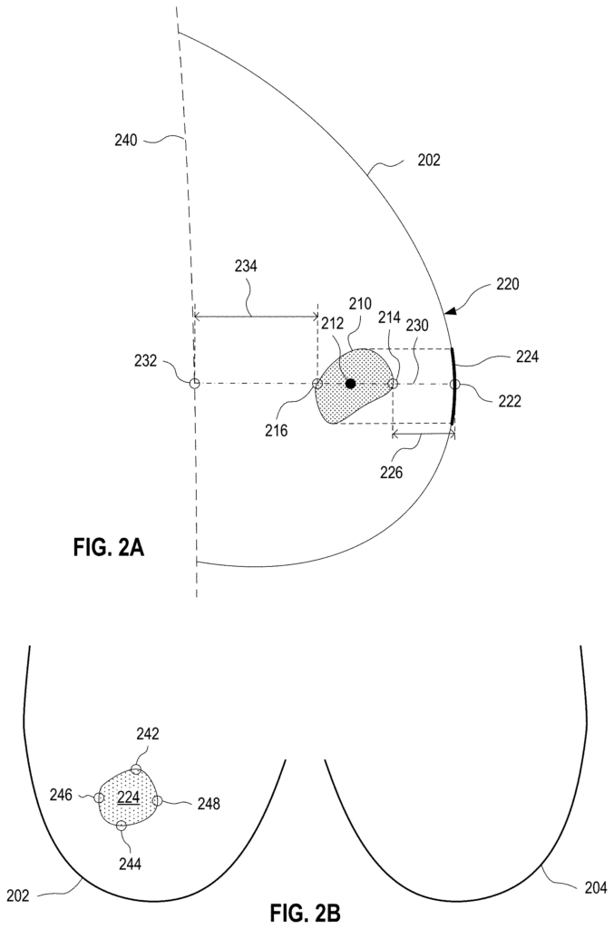
The distance between the anterior margin of the tumor 175 and the point where the line of sight 230 intersects its anterior perimeter (i.e. point of the tumor 210), which can be expressed as 226 between the anterior margin and the point 222.
Optionally a set surgical guidance cues (138) is included to indicate the projection. This includes one or more of its margins, such as the position cranial margin (the upwards extremity of the projection, which is upwards in the direction of the head of the patient), the caudal (downwards extreme) margin (which is downwards in the direction of the feet of the patients), the lateral (the most lateral part of the projection), and/or medial (the most middle
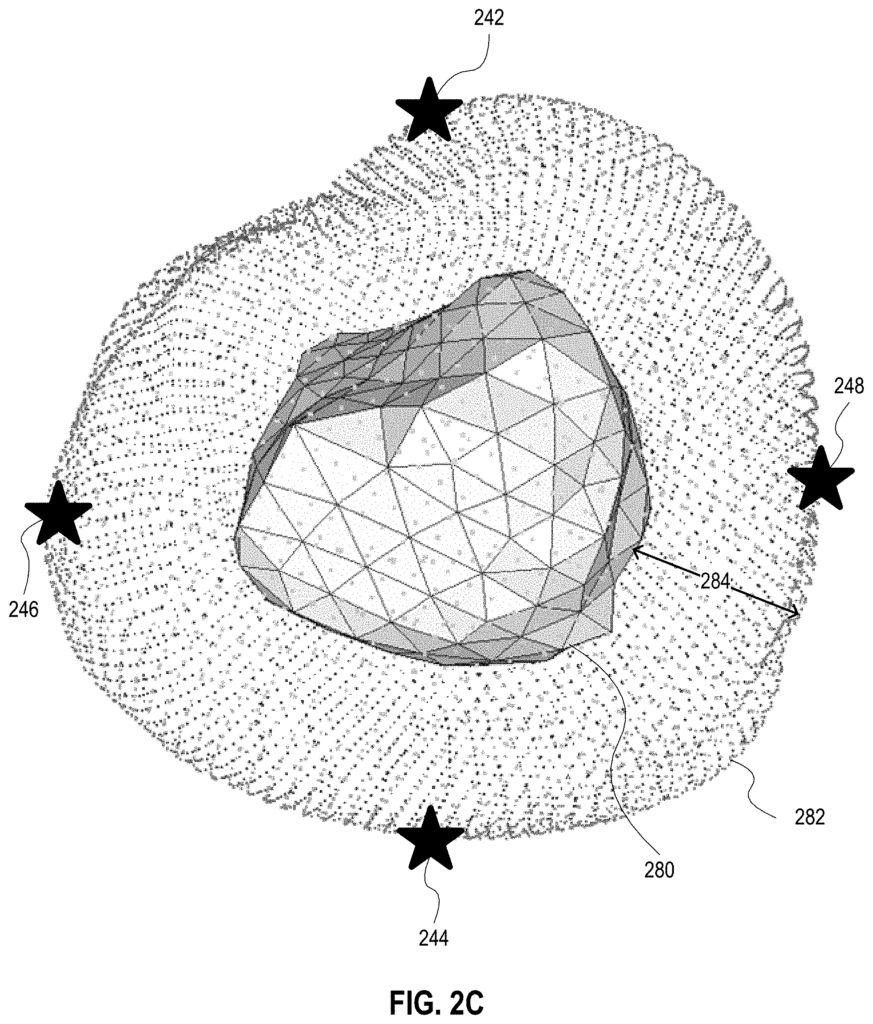
In certain examples, the definitions for cranial, caudal, lateral and medial borders are incorporated with a safety buffer. This means that the cranial, caudal, lateral and medial boundaries of the body, which is the tumor, is each defined as its respective extremes upwards, downwards and lateral plus a volumetric safety cushion. In some embodiments, the additional volumetric margin has a length of between 0.5 to 2.0 centimeters. The volumetric additional safety margin can be calculated by using a standard uniform-mesh resampling technique.
FIG. 2C illustrates exemplary tumor margins, which include a volumetric margin. A model 280 for tumor 175 has a volumetric margin 282 of thickness 284. Thickness 284, which can be between 0.5 to 2.0 centimeters, may have a centimeter-sized extent. The cranial margin 242, the caudal edge 244, the lateral edge 246, and the medial margin are respectively defined as upwards, downwards and lateral and medial extremities of safety margin 282. The safety margin 282 can be reduced by the breast 172 boundary in situations where tumor 175 is located relatively close to breast 172 boundary.
Other examples of surgical guidance cues (138) include the centroid 212 position, the outline of the tumor 210 and/or its full volumetric extent. Further, surgical guidance cues may include other positions to account for complex geometric tumors. In one example, surgical cues include other positions around the tumor 210 or inside the tumor 210. This can be in addition to the surgical cues previously discussed.
In an alternative embodiment point 222 is defined to be the point of incision for the resection operation to remove tumor 210. In this embodiment, the point 222 may not be the surface 220 point closest to tumor 210. The user may define the point 222. “For example, the surgeon 180 can choose an incision based on cosmetic considerations or considerations regarding the surface tissue of the breast 202 (for instance, the presence of scar tissues) or practical considerations like ease of access to incision point.
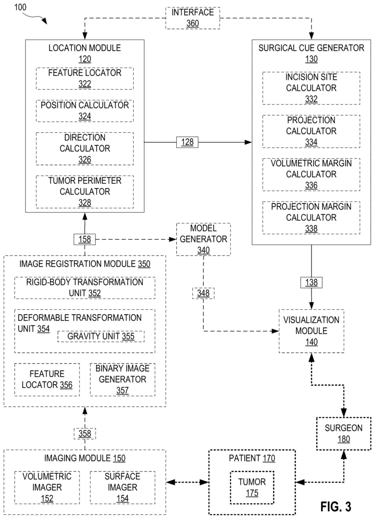
FIG. The system 100 is shown in greater detail on FIG. Location module 120 can include a feature locator 322 as well as a position and direction calculators 324 and 326. A tumor perimeter calculator is also included. Feature locator 322, for example, identifies features of supine images (158), such as tumor 175, and at least part of surface 174. Position calculator 324 calculates positions, such as centroid 212 or point 222. Direction calculator 326 calculates line of sight 230, and/or vectors along line of sight 230. Tumor perimeter calculate 328 determines position of perimeter of tumor 175, and/or specific points along the perimeter, such as anterior margins 214 and 216. The location module 120 can output 3D spatial properties 128, which are calculated by tumor perimeter calculator 328, position calculator 324, and direction calculator 326.
The “Surgical Cue Generator 130” may include an incision site calculater 332, a project calculator 334, a volumetric edge calculator 336, or a projection margin compute 338. The incision site calculator determines the optimal incision for resection surgery based on 3D spatial properties 128, to remove tumor 175. In one implementation, the incision is determined by point 222 as outputted by incision calculator 332. Projection calculator 334 calculates projection 224 using 3D spatial properties 128. For example, line-of-sight (230) determined by direction calculator 326, perimeter of the tumor 175 calculated by tumor perimeter calculator 3328, and positional information spatially related to the perimeter 175 of the tumor 220 determined by position calculator 324. Volumetric margin calculator 328 determines one or more margins for tumor 175 using 3D spatial properties 128, such as line-of-sight 230. In one implementation volumetric margin calculater 336 can determine distances 226 or 234. In this implementation, the volumetric margin calculator may calculate distance 226 to anterior margin 214, and point 222, as determined by tumor perimeter calculator 328 and position estimator 324. In this implementation, volumetric Margin Calculator 336 can also determine the distance 234 between posterior margin 216, and point 222, determined by tumor perimeter calculator 328 and position calculater 324. Volumetric margin calculator 336 outputs, in another example, the location of the anterior margin 214 or the posterior margin 216 as determined by the location module 120. The projection margin calculator 338 calculates the positions of the margins on the projection 224, such as the cranial margins 242, caudal edges 244, the lateral margins 246, or the medial margins 248, based for example upon the line-of sight 230 and the at least partial perimeters of the tumor 175 calculated by direction calculators 326 and 328. Position calculator 324 may provide additional information to the projection margin calculator 338 in relation to the surface 220 and tumor 175 perimeter. The surgical cue generator outputs as cues 138 one or more items that are determined by the incision site calculator 332 and projection calculator 334.
In certain embodiments of the system 100, a model generation 340 is included that processes an image 158 of at least a breast 172 in supine position to produce a 348 model. In one example model 348 comprises a volumetric image of at least a part of breast 172, including tumor 175 In another example model 348 comprises a 3D map of at lease a portion surface 174. In a further embodiment, the model 348 comprises a volumetric image of at least part of breast 172, including tumor 175, and at least some of surface 174. In another embodiment, the model 348 contains several of these maps. In one implementation of system 100, visualization module 140 is also included. Model generator 340 transmits model 348 from this implementation to visualization module so that module 140 can superimpose one or multiple surgical guidance cues on model 348. Visualization module may show model 348 to surgeon 180 with one of more surgical guidance clues 138 superimposed on it, and/or send model 348 along with one of more surgical guidance clues 138 to a navigation system for an operating room. The OR navigation system may include a tracking stylus whose position is tracked with respect to model 348 or surgical guidance clues 138. In this example, the tracking stylus can mark one of more surgical guidance clues 138 onto breast 172. The OR navigation system may also include an augmented-reality system, which superimposes the model 348 or surgical guidance cues on the viewfinder of the surgeon. The OR navigation system also includes a stereotactic tool, whose position is tracked with respect to model 348 or surgical guidance cues, so that the stereotactic tool may mark one of more surgical guidance clues 138 in or on breast 172.
In one scenario, the imaging module 150 captures each supine images 158. Imaging module 150 may capture one or more images 358, which will need to be processed in order to produce supine image 158. The position and shape may be different between the preoperative images of breasts 172, on which surgical guidance cues (138) are based at least in part, and the positioning during resection surgery. In one embodiment, system 200 includes an image registration component 350 that processes at least one image 358 captured while breast 172 was in a preoperative initial position and at the very least one additional image 358 captured when the breast 172 was in a substantially supine pose in which resection surgery takes place, in order to determine the supine images 158. Images 358 and 158 may be color or grayscale images.
In one example, image registration module 350 can register images taken by different imaging modes. Image registration module 350 can determine supine 158 in this example from a volumetric 358 image captured by volumetric 152 or third-party volumetric imaging device, where volumetric 358 was captured when breast 172 was substantially in the position of the resection. Image registration module 350 can also determine a 3D-surface image 358 captured either by surface imagers 154 or third-party surfaces, wherein 3D-surface image 358 was captured while breast 172 is substantially in position associated with resection surgery.
Click here to view the patent on Google Patents.
Leave a Reply