Invented by Jonathan George MARSH, Thomas Douglas Ridley, Sammantha Stephanie HARRIS, Boris Zukina, Christopher Daniel Currer WILKINSON, Dyson Technology Ltd
The cleaning appliance market is segmented into various categories such as vacuum cleaners, washing machines, dishwashers, steam cleaners, and others. Among these, vacuum cleaners are the most popular cleaning appliances, followed by washing machines and dishwashers. The demand for steam cleaners and other cleaning appliances is also increasing due to their effectiveness in cleaning and sanitizing surfaces.
The market for cleaning appliances is driven by various factors such as increasing urbanization, rising disposable income, and changing lifestyles. People are willing to spend more on appliances that can make their lives easier and more comfortable. Additionally, the growing awareness about the importance of hygiene and cleanliness is also contributing to the growth of the cleaning appliance market.
The cleaning appliance market is highly competitive, with several players offering a wide range of products at different price points. The market is dominated by established brands such as Dyson, LG, Samsung, Bosch, and Whirlpool. These brands have a strong presence in the market and offer innovative products that cater to the changing needs of consumers.
The cleaning appliance market is also witnessing a shift towards eco-friendly and energy-efficient appliances. Consumers are becoming more conscious of their carbon footprint and are looking for appliances that can help them reduce their energy consumption. This has led to the development of appliances that are designed to be energy-efficient and use eco-friendly materials.
In conclusion, the market for cleaning appliances is growing at a rapid pace and is expected to continue to do so in the future. The demand for these appliances is driven by various factors such as changing lifestyles, increasing urbanization, and rising disposable income. The market is highly competitive, with established brands offering a wide range of products at different price points. The shift towards eco-friendly and energy-efficient appliances is also contributing to the growth of the market.

The Dyson Technology Ltd invention works as follows
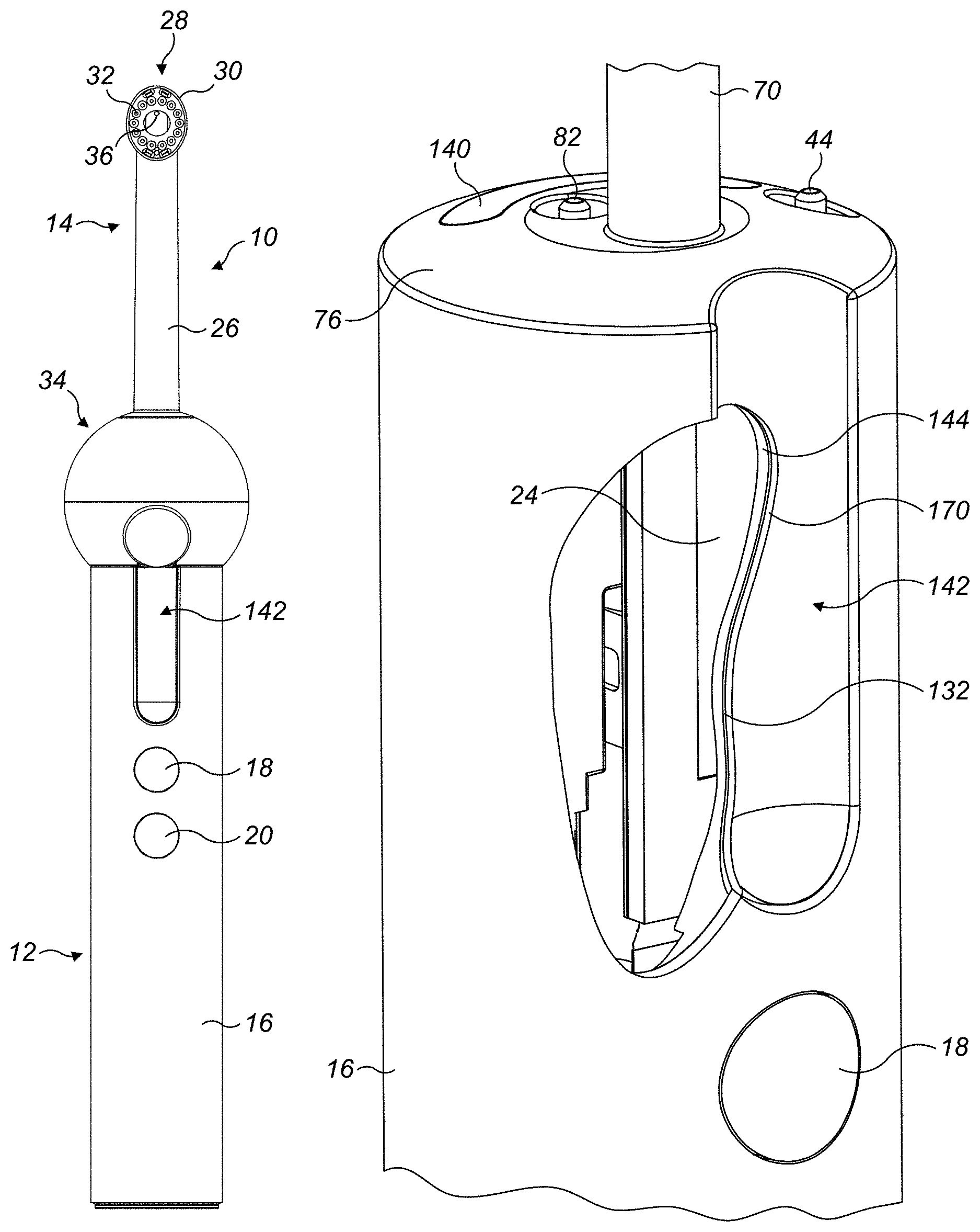
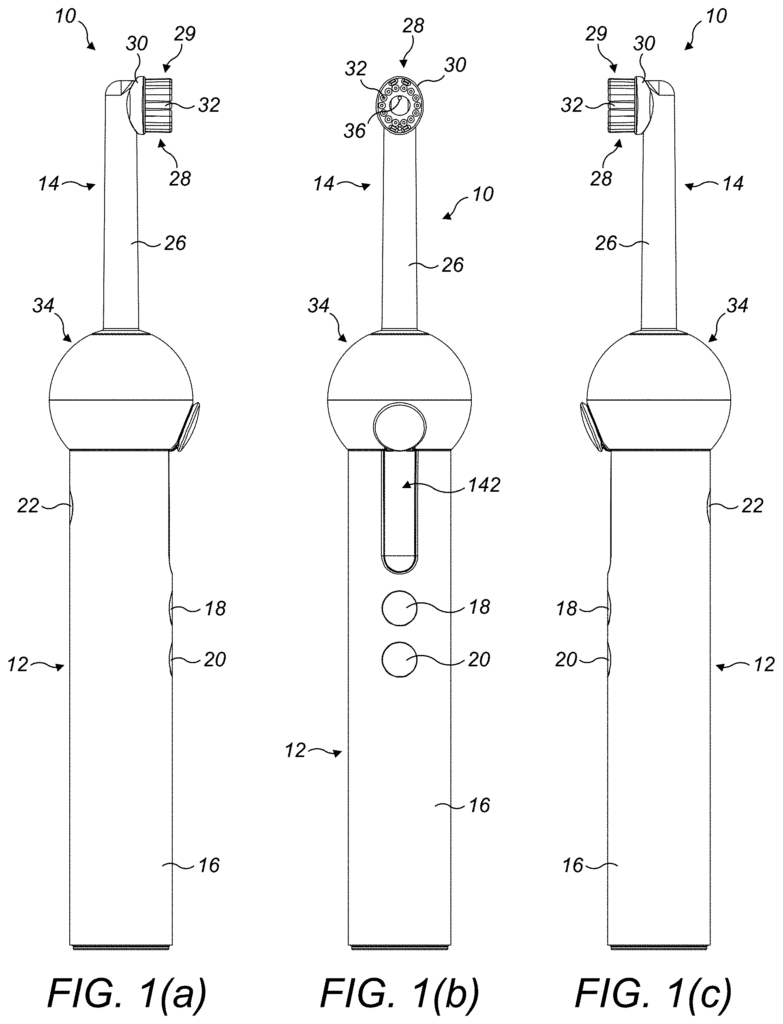
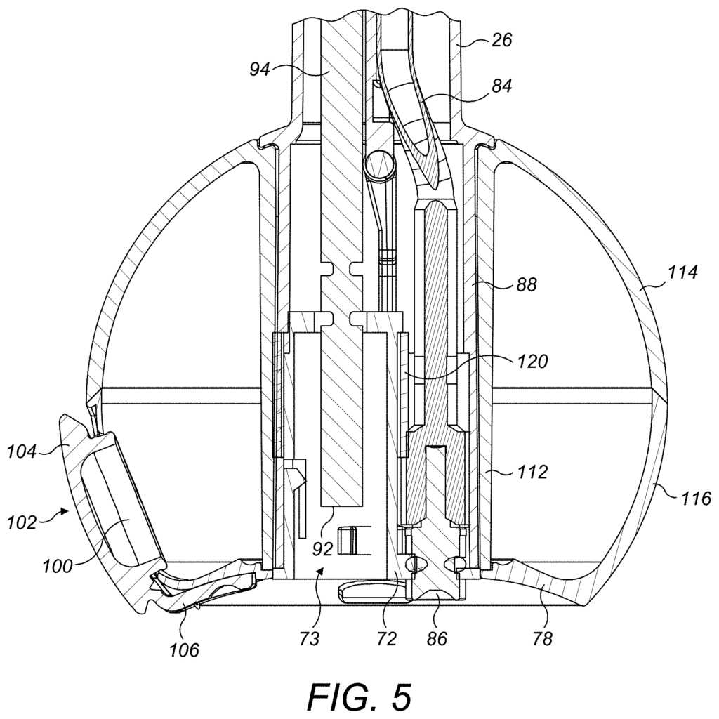
A dental cleansing appliance includes a handle, an electronic display and a control system for activating that display. The handle consists of a body with a transparent panel attached to it. The panel has a trough shape recess below which the display is situated.
Background for Cleaning appliance
Electric brushes generally consist of a cleaning tool that is attached to a handle. The cleaning tool consists of a stem, and a bristled brush head for brushing teeth. The brush head has a fixed section that is attached to the stem and at least one moveable part which can be moved relative to this section. This could be done, for instance, with a rotating, pivoting, oscillating or vibrating motion. The stem contains a drive shaft that couples with a unit of transmission within the handle. The transmission unit, in turn, is connected to a motor that is powered by a battery located within the handle. The transmission unit and drive shaft convert the rotary or vibrational motion of the motor to the desired movement of moveable section relative to static section of brush head.
It is well known that an electric toothbrush can be equipped with an assembly which generates a jet fluid to clean the interproximal area. U.S. Pat. No. No. A fluid path connects a fluid chamber with a nozzle on a static part of the brush. The pump is activated by the user using the actuator on the handle. It pumps fluid from the fluid compartment to the nozzle under pressure.
The present invention, in a first aspect provides a dental cleansing appliance that comprises a handle, a display, and a circuit to activate the display. Wherein the handle consists of a body connected with a transparent panel, the panel having a trough shaped recess. And wherein, the display is located below the recess.
The appliance is preferably equipped with a liquid reservoir, a port for replenishing the reservoir and a system to receive working fluid from it. Working fluid is usually a liquid such as water, or a solution of water. The recess in the transparent panel can be shaped so that working fluid is guided from the tap to the fluid port. This will make it easier to refill the fluid reservoir. The external surface of recess gets cleaned as the fluid flows over it.
The fluid port should be located on the external wall of a fluid reservoir. The fluid port can be fitted with a bung, or another closure device that is removable. This will prevent the working fluid from leaking out of the fluid reservoir. In a preferred configuration, the fluid container includes a closure that can be pivotally connected to the reservoir. The closure can move between an open position where the fluid port is exposed and a close position when part of the closure is inside the fluid port. The closure member should be located next to the recess on the panel to make it easier for the user to grip the closure member.
The fluid reservoir is preferably comprised of an arm that is connected to one end to the closure element and to the other end to the fluid storage. The fluid reservoir may be connected pivotally to the arm. The arm can also be flexible so that the closure member can move in relation to the fluid chamber. The arm can also include a hinge between its ends that allows the closure member and one end of said arm to pivot in relation to the other end and fluid reservoir. The arm of the closing member bends away from fluid reservoir as the closure moves from open to closed position. The handle recess is positioned preferably so that the closure member enters the recess when it moves from the open to closed position. This allows the arm to move freely relative to the reservoir.
The closure element may be made of resilient material in order to form a seal between the closure element and the fluid ports and allow the closure to flex as it moves from a closed to an open position. The closure member can also be made of a resilient sealant, such as an O-ring. This will form a fluid-tight sealing with the fluid port. The fluid port may be located on an external wall or side wall of a fluid reservoir. When the cleaning tool is attached to the handle, the arm can be connected to a bottom surface of the reservoir that faces and engages an end wall. When the closure member is closed, a portion of the elbow, preferably between the hinge and the other end of said arm, is preferably received in a recess of the bottom of fluid reservoir so that the bottom of the arm is flush with the bottom of fluid reservoir.
The recess has a cross section orthogonal to its longitudinal axis that is curvy and preferably concave. The recess of the handle is preferably defined as a concave panel. The concave surface extends preferably substantially the entire length of the recess. The concave walls has a cross section that is arcuate, with a radius of curvature that is preferably between 5 and 10 mm. The thickness of the concave wall is preferably in the range between 1 and 2 mm.
The handle body is convex. The handle is generally cylindrical, but it can have a cross-section that is orthogonal to its longitudinal axis, such as polygonal or elliptical. The cross-section can be symmetrical, asymmetrical, or both. The radius of curvature for the concave walls is smaller than that of the body. The radius of curvature is preferably between 10 and 20 mm. The thickness of a body is preferred to be in the range between 0.7 and 1.5 mm.
The panel should be made from a material different from that of at least a portion of the handle’s body adjacent to it.” The panel is overmolded onto the handle, preferably at least that portion of the handle which adjoins it, but more preferably, the entire body. The body of the handle is preferably formed from an amorphous material, such as a blend of polycarbonate (PC) and acrylnitrile-butadiene-styrene (ABS) materials. Panels are preferably made of transparent polycarbonate. The end surface of the body is preferably located next to the fluid reservoir. The recess is preferably adjacent to the end surface of body. The handle is preferably equipped with an end wall at the end of body that is distant from the recess. The end wall can be detached from the body so that a user can replace the battery within the handle.
The handle is preferred to include at least one button that can be operated by the user. This button has a flexible membrane, which the user presses in order to activate the button. In a preferred version, the handle consists of a number of these buttons that are all defined by a single membrane. Preferably, the membrane is molded onto the panel or vice versa. This is done before the body overmolds on the panel. The handle can be made up of a number of flexible membranes that are overmolded onto the panel or on which the panel has been overmolded. Membranes may be placed on either side of the panel. The flexible membrane, or each of them, is preferably made from a thermoplastic rubber material.
The handle body may be painted. The paint layer is useful when the body has been formed of an amorphous substance. It can protect the body from chemical attacks. Before painting the handle body, the exterior surfaces of the panel or flexible membrane are covered to prevent them from being painted. After the mask is removed, a reflective layer can be placed on the external surface of a panel. This allows the user to see the display when it’s activated. The handle can be improved visually by using this method. When the display has not been activated, it cannot be seen through the reflective layer. However, when the display has been activated, the user is able to see the display through the reflective layer.
The present invention, in a second aspect provides a dental cleansing appliance that comprises a handle, a display, and a control system for activating the displayed. Wherein the handle consists of a body, which is gripped during the use of the appliance by the user, a panel transparent beneath which the display resides, and an external layer of reflective material on the panel, through which, when used, the activated screen is visible to the users.
The reflective layer preferably has at least 70% transmissivity.” The reflective material’s transmissivity is best in the 70-90 range, and more specifically in the 75-85% range. The reflective layer is applied to the panel by a printing or hot stamping method. The reflective material can be made from either polyester or polycarbonate, which will form a thermochemical bond to the panel material during the hot stamping procedure.
The foil or layer reflective material should be applied to the panel only after the handle body has been painted and any masking materials have been removed. The panel of transparent material can be overmolded onto a foil of reflective material before the membrane is formed.
As an alternate to painting the handle body, the handle body can be made from a semicrystalline material such as a polyester, PCTG, or PET. The foil of reflective material can be applied after the panel has been formed.
A transparent scratch resistant coating can be applied to the reflective foil and body. The scratch-resistant material can be silicone. “Rigid end cap can also be attached to the exposed surfaces using glue or other adhesives.
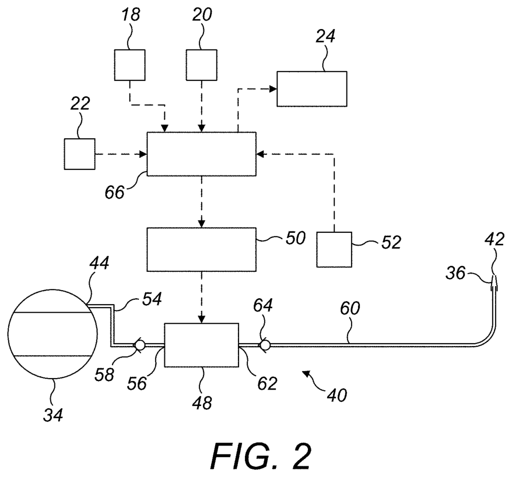
The display is an electronic screen that is activated by a control circuit in order to display information for a user. The display is preferably an elongate OLED display.
The appliance is preferably equipped with a cleaning tool attached to the handle. The cleaning tool is preferably made up of a head and a stem that extends between the handle and the head. The fluid reservoir is preferably part of the cleaning tool. The fluid reservoir should be connected to the stem and extend around it. The fluid delivery system is preferably integrated into the head to deliver a burst or working fluid directly to the user’s teeth. The liquid working fluid is water or water solution.
The fluid-delivery system comprises preferably a pump, and a control module for activating the pump so that it draws working fluid from the reservoir and ejects a burst towards the nozzle. The user can depress one button to activate the pump and cause the working fluid to be ejected as the nozzle moves between adjacent teeth. The appliance can also be programmed to automatically deliver working fluid to user’s teeth based on the output of a sensor that detects the nozzle within the interproximal space. The sensor can be a light-detecting device, such as a camera, or a sensor that receives light emitted by a user’s mouth. The appliance can also be configured to deliver working fluid automatically to the teeth at a predetermined frequency, such as between 0.5 to 5 Hz.
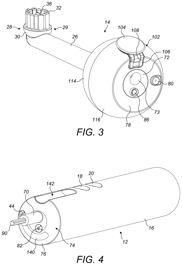
The appliance can be a special interproximal cleaner that cleans between the gaps of the user’s tooth. The appliance can also be in the shape of a toothbrush that has an added function to improve interproximal cleansing by releasing a burst working fluid into the gap. The cleaning tool is preferably a plurality bristles when the appliance takes the form of toothbrush. The bristles can be arranged in a circular pattern around the nozzle or preferably, they are arranged around it. The bristles can be attached to an area of the cleaning tool that is static and not movable in relation to the handle. A plurality of brushes may also be attached to the moveable section of a cleaning tool. The appliance is preferably a brush unit that includes a bristle-carrier and multiple bristles mounted thereon, where the bristle-carrier can be moved relative to the handle.
Click here to view the patent on Google Patents.
Leave a Reply