Invented by Gregory William Coombe, Chen Chen, Derik SCHROETER, Jeffrey Minoru Adachi, Mark Damon Wheeler, Nvidia Corp
ICP-based lidar systems use laser sensors to create a 3D map of the environment. The ICP algorithm then compares the data from multiple scans to create a more accurate and detailed map. This technology is particularly useful for creating high-definition maps that are necessary for autonomous vehicles and robotics to navigate safely and efficiently.
However, one of the challenges with ICP-based lidar systems is that they can be affected by movement. Any movement of the lidar sensor can cause errors in the data, leading to inaccurate maps. To address this issue, some companies are integrating movement estimation technology into their lidar systems.
Movement estimation technology uses sensors to track the movement of the lidar sensor and compensate for any movement during the scanning process. This results in more accurate and reliable data, which is essential for creating high-definition maps.
The market for ICP-based lidar with integrated movement estimation is expected to grow significantly in the coming years. According to a report by MarketsandMarkets, the global lidar market is expected to reach $2.8 billion by 2025, with a CAGR of 17.2% from 2020 to 2025. The report also highlights the increasing demand for high-definition maps for autonomous vehicles and the need for more accurate and reliable lidar systems.
Several companies are already offering ICP-based lidar systems with integrated movement estimation. For example, Velodyne Lidar’s Alpha Prime? lidar sensor uses ICP technology and has an integrated IMU (Inertial Measurement Unit) for movement estimation. The sensor can capture up to 300,000 points per second and has a range of up to 300 meters.
Another company, Cepton Technologies, offers the Vista-X90 lidar sensor, which also uses ICP technology and has an integrated IMU for movement estimation. The sensor has a range of up to 200 meters and can capture up to 1.2 million points per second.
In conclusion, the market for ICP-based lidar with integrated movement estimation for high-definition maps is growing rapidly. As the demand for more accurate and reliable lidar systems increases, we can expect to see more companies entering this market and developing innovative solutions to meet the needs of various industries.

The Nvidia Corp invention works as follows
A system that aligns point clouds from sensors on a vehicle by using kinematic closest point estimations with integrated motion estimates.” The lidar scans are received by the system from a mounted lidar. The system creates point clouds using the data from lidar scans. Iteratively, the system determines velocity parameter that minimizes an aggregate measure distance between points in a plurality of pairs. The system improves velocity parameters iteratively. The system uses velocity parameters in various ways, including to build high-definition maps that are used for navigation.
Background for Iterative close point process based lidar with integrated movement estimation for high-definition maps
This disclosure is a general description of the alignment of point cloud generated by a mounted lidar on a vehicle in motion, and more specifically a technique that iteratively calculates closest points with integrated motion estimation.
Autonomous cars” (also known as driverless cars or autos) are vehicles that drive themselves from one location to another without the need for a driver. The automation of driving is not easy for several reasons. Autonomous vehicles, for example, use sensors to make decisions about driving on the fly. However, vehicle sensors can’t see everything at all times. Corners, hills and other vehicles can obscure vehicle sensors. The sensors on vehicles may not be able to detect certain things in time for them to make a decision. Sensors may not be able to detect lanes or signs that are missing, or have been knocked down or covered by bushes.
Autonomous cars can use map data instead of sensor data to determine some of the information above. Maps are not ideal for autonomous vehicles because they have many limitations. Maps, for example, do not have the accuracy needed to ensure safe navigation (10 cm or less). GPS systems have an accuracy of 3-5 meters but large error conditions that result in a location accuracy of more than 100 metres.
Techniques for creating maps use iterative closest point (ICP) techniques for processing point clouds. Sensor data from a vehicle, such as lidar scans, is used to generate point clouds. Rotational lidars such as VELODYNEHDL sweep the surrounding area by firing lidar beams on a circular basis. Each laser beam measures the distance between the object that is reflective and the lidar’s center. As the lidar spins, it produces a stream points that are then split into point cloud. Each point of a lidar that is stationary is relative to one scan center. For autonomous driving, however, the lidar will be mounted on top a rotating vehicle, and the scan center is determined by the rotation of the vehicle. In the conventional ICP method, each point cloud is treated as a single centre. The measured point clouds from lidar are not in line with reality. To know where the center points are, the system needs to know the motion of the path.
Conventional methods first estimate the motion using raw point clouds, then apply the motion to the points, and repeat this process. This process is unstable, and iterating a few more times can result in increasing errors. Conventional techniques fail to align the point clouds and cause inefficiencies, which slow down computation convergence. The conventional techniques can also result in errors during the alignment process, which then cause errors in the generated high-definition maps.
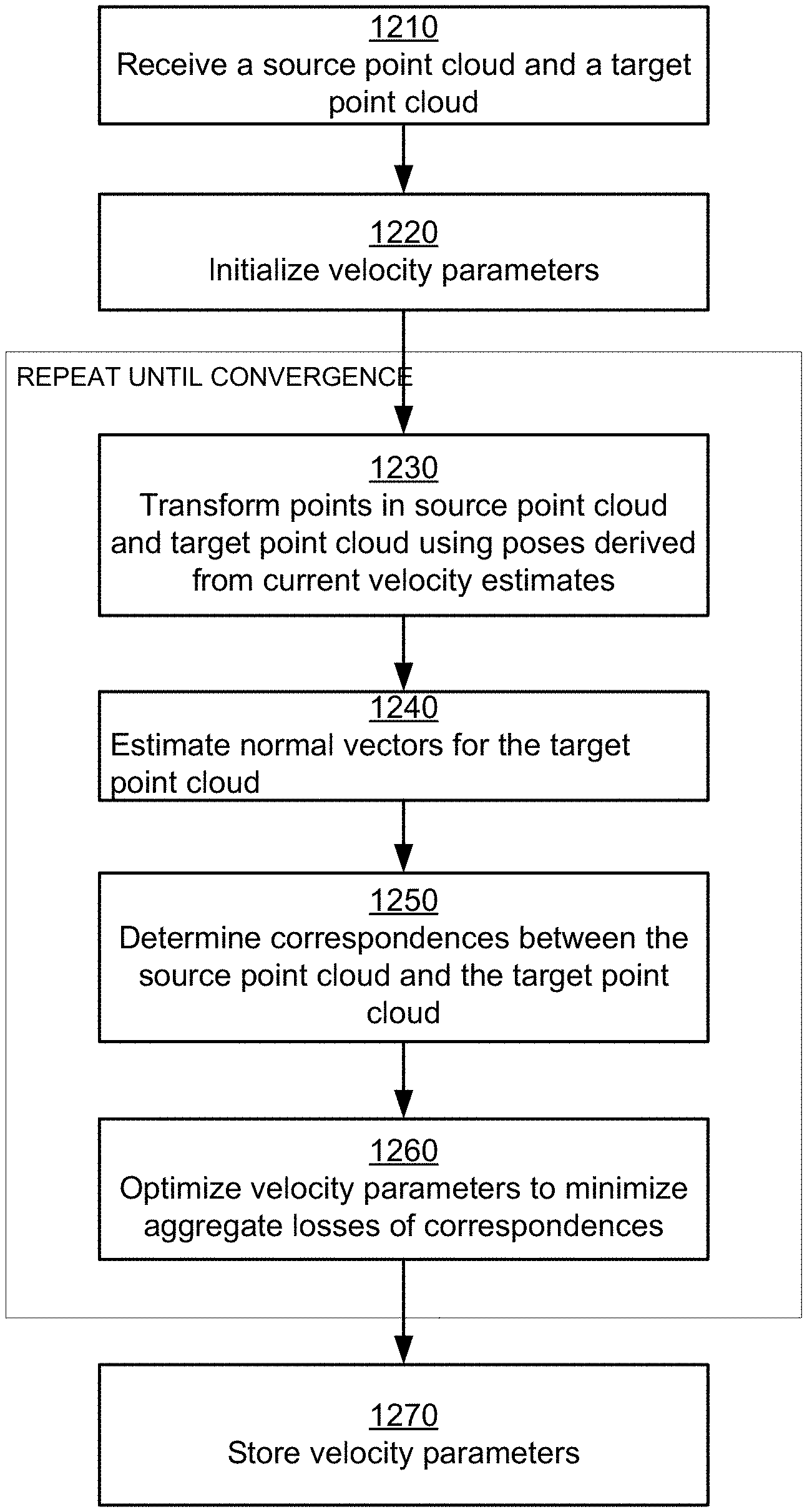
Embodiments” of the invention aligns point clouds derived by sensors of an autonomous vehicle using kinematic closest point technique and integrated motion estimates. Sensor data about the environment around an autonomous vehicle is received by a lidar mounted to that vehicle. Sensor data includes a plurality points, and each point has a time associated with it. A source point cloud is determined by the system based on a plurality of data points. The system initializes multiple velocity parameters that describe the movement of an autonomous vehicle.
The system repeats these steps for multiple iterations.” The system establishes a number of correspondences. Each correspondence represents a pair of points. The pair of point includes a source point cloud point and a target point cloud point. The system modifies velocity parameters in order to optimize the aggregate distance between the corresponding pairs of points. The steps are repeated until the error measure between two point clouds is below a threshold.
The system calculates the control signals to navigate the autonomous vehicle using the velocity parameters, and then navigates the vehicle using the control signals. The system can, for example, use the kinematic ICP to align point cloud data that is used to create high definition maps. The high-definition maps are used by the autonomous vehicle for navigation.
In one embodiment, the system adjusts the velocity parameters to at least one point cloud of either the source or target. The adjustment involves transforming the points in the point cloud according to the velocity parameters as well as the time at which the point was captured. The system, for example, uses the velocity parameter to estimate the distance traveled by an autonomous vehicle between a capture time and a reference point. The reference point can be the time of capture of last point in the point cloud, which represents the completion of capture. The system moves a point in a point-cloud by an estimated distance.
In one embodiment, the system optimizes the distance measure between correspondences by using a nonlinear optimization technique such as gradient descent. In one embodiment, the system optimizes velocity parameters using constraints that limit the velocity parameter estimates to maximum velocity parameters determined by physical movement of an autonomous vehicle.
In one embodiment, the system initializes a plurality of speed parameters based either on data from the inertial measuring unit of the vehicle or based upon the global navigation satellite system.
In one embodiment, the system measures the distance between two corresponding points in a point cloud by determining the normal direction of the surface at the target and then determining the distance between the source and target along the normal direction.
In one embodiment, the system determines if a target of the cloud of target points is the nearest neighbor to the source of that cloud and if the source of the cloud of source points is the nearest neighbor to the target.
Although different embodiments of the invention are described with respect to autonomous vehicles, these techniques are also applicable to other navigable machines, such as other types of vehicles or robots, that can receive sensor signal, for example lidar signals, and navigate using the sensor signals. Moreover, embodiments described herein use lidars as sensor. The techniques are also applicable to other sensors, for example a pair cameras such as left-right cameras that can generate 3D coordinates by triangulation.
Embodiments” of the invention keep high-definition (HD) maps with up-to date information, using high precision. These HD maps can be used to navigate autonomous vehicles safely to their destination without the need for human input. A vehicle that is autonomous can sense its environment and navigate without human input. Herein, autonomous vehicles are also referred to as “driverless cars.” ?self-driving car,? Or a ‘robotic car.’ A HD map is a map that stores data at a very high level of precision, usually 5-10 cm. Embodiments create HD maps that contain spatial geometric information on the roads where an autonomous vehicle is able to travel. The generated HD maps contain the necessary information for an autonomous vehicle to navigate safely without human interference. Embodiments create and maintain accurate high definition (HD), maps, which include the latest road conditions to ensure safe navigation.
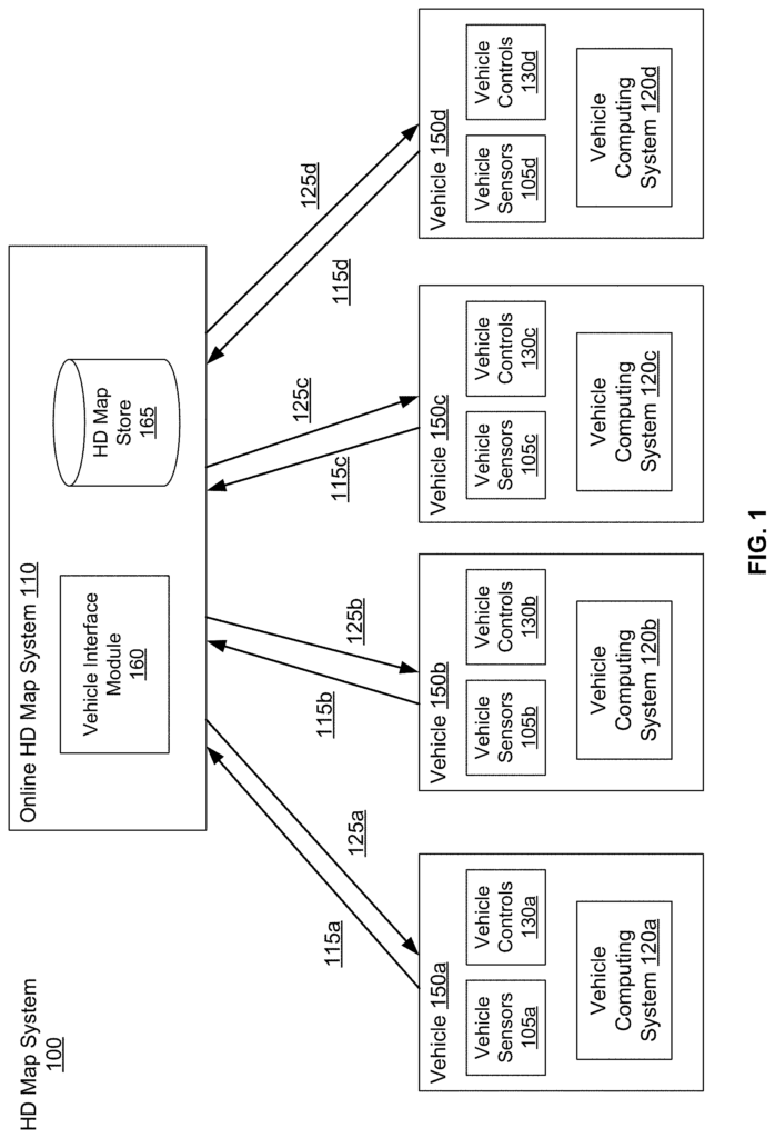
FIG. According to one embodiment, Figure 1 depicts the overall system environment for an HD map system that interacts with multiple vehicles. The HD map 100 system includes an online HD mapping system 110 which interacts with multiple vehicles 150. Vehicles 150 can be autonomous, but they are not required. The online HD mapping system 110 receives data from sensors on the vehicles and then combines it with the data collected by the vehicles to create and maintain HD maps. The online HD mapping system 110 transmits HD map data from the vehicle to be used in driving. In one embodiment, the online HD mapping system 110 is implemented using a distributed computing service, such as a cloud-based service, which allows clients, like vehicle computing systems 120, to request information and services. “For example, the vehicle computing system 120 can request HD map data to drive along a route. The online HD map 110 will provide the HD map data requested.
FIG. The same reference numbers are used to identify similar elements in Figure 1 and other figures. After a reference number, e.g.?105A?, a letter is added. The text will refer to the specific element with that reference number. Referential numbers in text that do not have a letter following them, like?105?, are called’reference numerals. Refers to all or some of the elements within the figures that bear the reference number (e.g. ?105? In the text,?105? and/or ?105N?
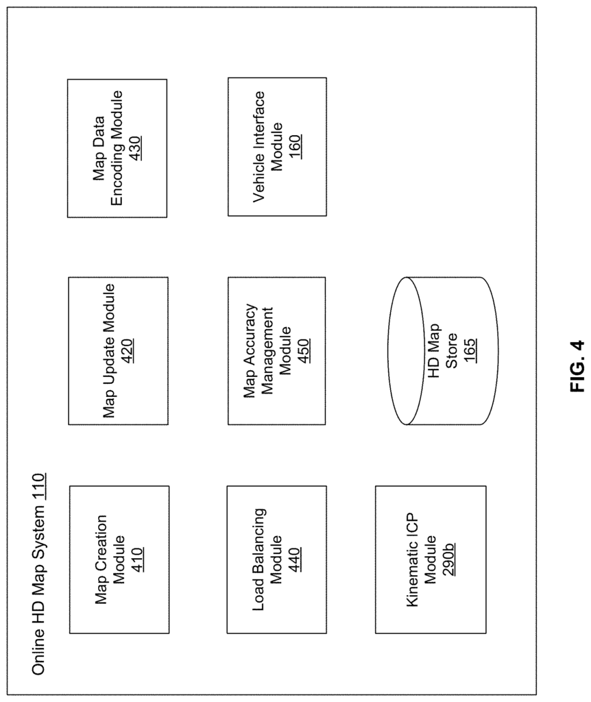
The online HD mapping system 110 comprises an HD map store and a vehicle interface 160 module. The vehicle interface module 160 allows the online HD map system to interact with the computing system 120 in various vehicles 150. HD Map Store 165 is where the online HD map system stores maps for different geographical regions. The online HD mapping system 110 can include modules other than those in FIG. The online HD map system 110 may include other modules than those shown in FIG. “Figure 4 and described further herein.
The online HD mapping system 110 receives data collected by sensors from a multitude of vehicles 150. For example, hundreds of thousands of cars. The vehicles send the sensor data they capture while driving on different routes to the online HD mapping system 110. The online HD mapping system 110 creates and updates HD maps using the data from the vehicles to describe the areas in which they are driving. The online HD mapping system 110 creates high-definition maps using the information collected from vehicles 150. It stores this information in HD map store 165.
The online HD mapping system 110 sends HD maps as requested by vehicles 150. If, for example, an autonomous vehicle is required to travel a certain route, then the vehicle computing system of the autonomous car provides the information about the route to the online HD mapping system 110. The online HD map 110 then provides the HD maps required for driving along the route.
![]()
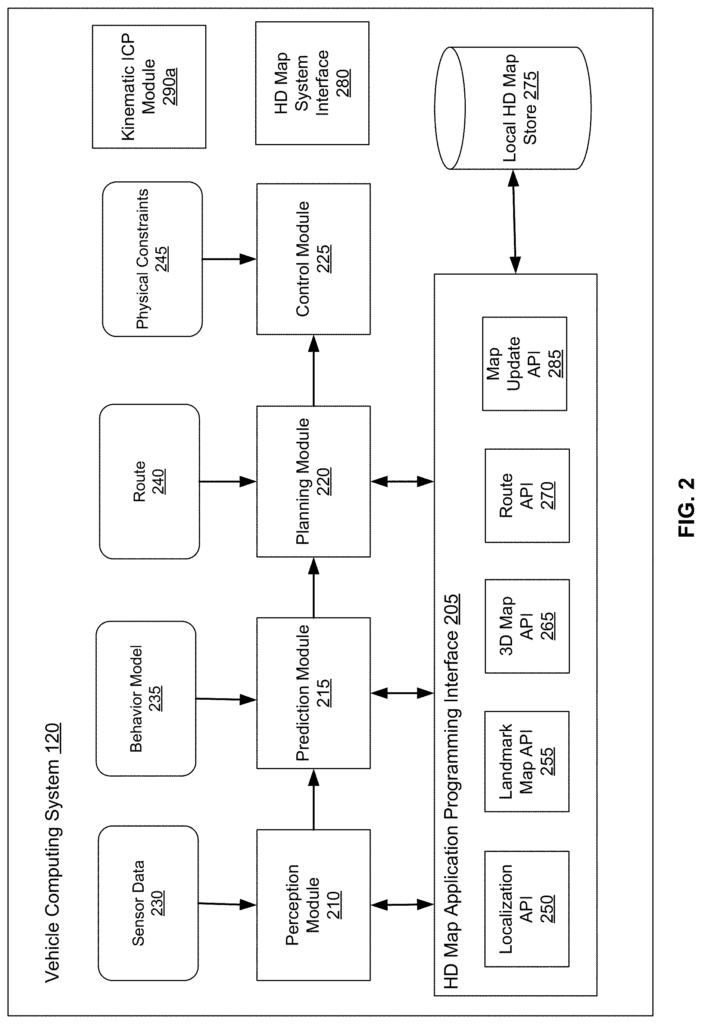
In one embodiment, the online HD mapping system 110 transmits HD map data in a compressed form to vehicles so that data transmission is reduced. The online HD mapping system 110 receives information from vehicles describing data stored in the local HD store 275. The online HD system 110 will send a portion of HD map to a vehicle if it determines the vehicle has not stored corresponding data locally at the local HD store 275. The online HD mapping system 110 can determine that the vehicle has previously received that portion of HD map, but that the corresponding data have been updated since the vehicle was last provided with the data. In this case, the online HD mapping system 110 will send an update to the HD maps stored in the vehicle. The online HD map system can then minimize the amount data sent to the vehicle, and keep the HD maps stored in the vehicle up-to-date on a regular schedule.
Click here to view the patent on Google Patents.