
Invented by Richard Galera, Anne Bowlby, Derek W. Jones, Nilesh Pradhan, Francis L. Leard, Rockwell Automation Technologies Inc
Optical area monitoring systems use advanced cameras and sensors to monitor a specific area and detect any objects or movements within that area. These systems are commonly used in industries such as manufacturing, logistics, and construction to ensure the safety of workers and prevent accidents. By integrating optical area monitoring with industrial machine control systems, companies can further enhance safety measures and improve overall operational efficiency.
One of the key advantages of integrating optical area monitoring with industrial machine control is the ability to automate safety protocols. With this technology, machines can be programmed to automatically stop or slow down when an object or person enters a restricted area. This not only reduces the risk of accidents but also minimizes downtime and improves productivity. Additionally, by integrating these systems, companies can ensure compliance with safety regulations and avoid costly penalties.
Another benefit of this integration is the ability to gather real-time data and analytics. Optical area monitoring systems can provide valuable insights into the movement of objects and people within a specific area. By integrating this data with industrial machine control systems, companies can optimize workflows, identify bottlenecks, and make informed decisions to improve operational efficiency. For example, if a certain area is frequently congested, adjustments can be made to the machine control system to optimize the flow of materials or personnel.
Furthermore, integrating optical area monitoring with industrial machine control can enhance quality control processes. By monitoring the movement of objects and materials, companies can identify potential defects or errors in real-time. This allows for immediate corrective actions, reducing waste and improving overall product quality. Additionally, by analyzing the data collected from the monitoring systems, companies can identify patterns or trends that can help optimize production processes and minimize errors.
The market for integration optical area monitoring with industrial machine control is expected to continue growing in the coming years. The increasing focus on workplace safety, efficiency, and productivity is driving the adoption of these technologies across various industries. Additionally, advancements in camera and sensor technologies, as well as the integration capabilities of industrial machine control systems, are further fueling the market growth.
In conclusion, the integration of optical area monitoring with industrial machine control systems offers numerous benefits to companies across various industries. From enhancing safety protocols and automating processes to improving operational efficiency and quality control, this technology is revolutionizing the way businesses operate. As the market continues to grow, companies that embrace this integration will have a competitive advantage in terms of safety, productivity, and overall business performance.
The Rockwell Automation Technologies Inc invention works as follows
An industrial system that integrates optical safety with machine control is provided.” The safety system contains an imaging sensor device that supports pixel-array processing functions. This allows time-of flight (TOF), analysis to be performed only on certain portions of a pixel-array, while two-dimensional image analysis is performed for the remainder of the array. This reduces processing load and response times compared to TOF analysis performed on all pixels in the array. The imaging sensor device can either be configured to select the portion of the array that will be used for TOF analysis, or it can be selected dynamically based on the object detection and classification performed by the two-dimensional image analysis. The imaging sensor device may also implement safety and redundancy features to achieve a higher degree of safety integrity.
Background for Integration optical area monitoring with Industrial Machine Control
The subject matter disclosed in this invention relates to industrial safety and, specifically, to the integration of industrial control systems with optical area monitoring by using an imaging system capable of performing time-of flight (TOF), selective analysis of specified portions of a pixels array.
BRIEF DESCRIPTION
The following is a simplified overview to help you understand some of the aspects discussed here. This summary does not provide an exhaustive overview, nor is it meant to highlight key/critical aspects or define the scope of various aspects. The sole purpose of this summary is to simplify some concepts as a precursor to the detailed description which will be presented later.
The optical safety system includes a pixel-array component that groups pixels in one or multiple pixel-arrays captured by one of more imaging sensors devices to produce a subset on which 2D analyses are to be performed, an image analysis component that performs 2D analyses on the subset, a distance determination module configured to perform 3D calculations on point cloud data from the imaging sensor device, and a decision and analysis component for hazard classification based on the 2D and 3D results.
The method includes: collecting image data from one- or more sensor devices monitoring a hazardous zone, performing a two-dimensional (2D), and a three-dimensional (3D), analysis of selected pixels; calculating distances for the pixels calculated by the sensor devices, and performing a 3D, analysis of point cloud data; classifying the first object as a person based at least on one of either the 2D or 3D analyses; classifying the second object as motorized machinery based at least on one of both the 2D and 3D, based based based on one-dimensional data based on one-dimensional data based based based based based based based based based based based based based based based a based based based based a based based based a based a motorized based a a based based based based based a 2D,
The non-transitory medium also includes instructions that when executed, cause a computer system to perform certain operations. These operations include: collecting image data from one- or more imaging sensors monitoring a hazardous area; performing 2D (2D) image analysis on selected pixels; performing 3D (3D), analysis of point cloud data containing distance information; classifying the first object of the image as a person based at least on one of 2D or 3D image analysis; and classifying the second object of the image as motorized machinery based at least on either the 2D or 3D (3D, 3D (3D, 3D (point cloud data based on based at least on at least based at least on at least based at least one-based on a based based based based based based based based based based based based based based a motorized industrial equipment, based at least based at least on 2D based 3D based based based a third object) 2D, or 3D, 2D, or 3D, 2D, 3D, 2D,
In order to achieve the above and related goals, certain illustrative elements are described in the following description as well as the annexed illustrations. These aspects represent various methods that can be used, and all are intended to covered in this document. “When viewed in conjunction with the illustrations, the detailed description may reveal other advantages and novel features.
The subject disclosure will now be described in reference to the drawings. Like reference numbers are used throughout to refer to similar elements. To provide a complete understanding of the subject disclosure, many specific details will be provided in the following description. However, it may be obvious that the disclosure in question can be implemented without these details. Other times, well-known devices and structures are shown as block diagrams to make a description easier.
The terms “component” and “system” are used interchangeably in this application. ?system,? ?platform,? ?layer,? ?controller,? ?terminal,? ?station,? ?node,? ?interface? Interfaces are meant to be a computer or entity that is related to or part of an operational apparatus, with one or several specific functionalities. These entities can either be hardware, a combination between hardware and software or software. Components can include, but are not limited to, a program running on a CPU, a hard drive, multiple storage devices (of magnetic or optical storage medium), including fixed (e.g. screwed-in or bolted-in) or removable solid-state drives, an object, an executable, a thread, an executable program and/or computer. As an example, a server application and the server itself can both be components. A component may reside in a thread or process. It can also be localized to one computer or distributed across two or more computers. Components described herein may also be executed from a variety of computer-readable storage media that have various data structures thereon. Components may communicate using local or remote processes, such as a signal with one or more packets of data (e.g. data from one system interacting with another system in a distributed system and/or over a network, such as the Internet, with other systems). Another example is an apparatus that provides specific functionality through mechanical parts controlled by electronic or electric circuitry, which are operated by software or firmware applications executed by a computer. The processor can be either internal or external to apparatus, and can execute at least part of the application. Another example is an apparatus with specific functionality provided by electronic components, without mechanical components. The electronic components may include a processor to execute software or hardware that provides the functionality. Interfaces can also include I/O components, processors, applications, and Application Programming Interfaces (API) components. The examples above are directed at aspects of a particular component. However, these aspects or features can also be applied to a platform, interface layer, controller, terminal and other similar systems.
As used herein the terms ‘to infer? “To infer?” and “inference?” are used interchangeably herein. Inference refers to reasoning about or inferring the states of a system, environment, or user from a collection of observations captured through events and/or other data. Inference can be used to identify a context or act, or generate a probability distribution of states. Probabilistic inference is the calculation of a probability distribution for states of interest using data and events. Inference may also be used to construct higher-level events using a collection of data and events. This inference allows for the creation of new events or actions using a collection of events and/or data. It does not matter if the events are closely correlated or if the data comes from one or more event and data sources.
In addition, the expression?or? “In addition, the term?or? is meant to refer to an inclusive?or. It is not intended to be an exclusive ‘or.? This means that the phrase ‘X employs A and B, unless otherwise stated or made clear by the context. is meant to refer to any of the natural inclusive permutations. The phrase “X uses A or B?” is intended to mean that the phrase “X” can be used in any of the natural inclusive permutations. X employs either A or B, or both A and B. The articles?a? Additionally, the articles?a????? and?an?? As used in this application and the attached claims, it should be understood to refer to?one or more? Except where otherwise stated or made clear by context, the meaning of “one or more” is to refer to a single form.
Furthermore the term’set? The term?set? as used herein excludes an empty set, i.e., a set that has no elements. A?set? is thus defined. A?set? in the subject disclosure can refer to one or more elements, entities or combinations. A set of controllers may include one or more controllers. A set of data resources can contain one or more data resource. The term “group” is also used herein. As used herein, the term “group” refers to a collection or combination of entities. For example, a group consisting of one or several nodes.
Various features and aspects will be described in terms of systems, which may include multiple devices, components, or modules. It should be understood that different systems could include additional components, modules, or devices. All of the components, devices, modules, etc. may not be included. These are discussed in conjunction with the figures. These approaches can also be combined.
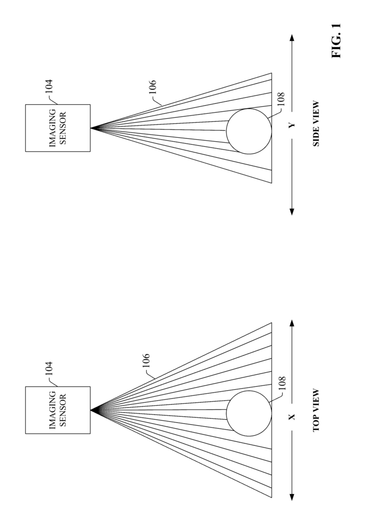
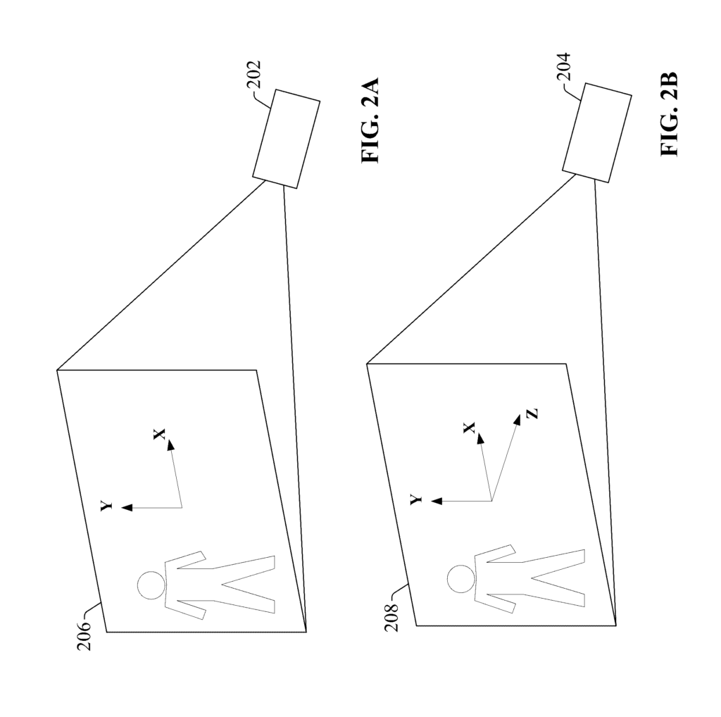
Two-dimensional imaging sensors (2D) are used to detect and identify surface and/or shape characteristics of objects in a sensor’s viewing field. FIG. FIG. Some 2D imaging sensors, such as imaging cameras, operate by projecting an expansive light beam 106 towards the area to be monitored, and then collecting the light reflected off surfaces and objects within the viewing region (e.g. object 108) at a receiver. Some sensors sweep the beam 106 in an oscillating manner across the viewing area to collect image data. This information is then analyzed to identify edges, surfaces, patterns on the surface, and other similar information. The sensor 104 can also project a substantially plane beam of light over an area of interest, and collect data about objects that pass by the beam. 2D image sensors generally perform grayscale analysis or red-green blue (RGB), based on pixel data, to produce two-dimensional images for the viewing area. These can then be analyzed in order to identify edges, surface patterns, contours or other information. FIG. 2A shows a schematic of 2D image processing using a 2D sensor 202. 2D image processing yields surface and object information in the xy plane. The sensor outputs will vary depending on the application.
Three-dimensional (3D), also called time-of flight (TOF) sensor, is designed to provide distance information and two-dimensional shape data for surfaces and objects within the viewing field of the sensor. Some TOF sensors measure distances using phase-shift monitoring. A beam of light is sent into the viewing field and the phase shift measured between the light reflected by the object and the light emitted is then translated into a value. Some TOF sensors use pulsed illumination to measure the time between the emission of the light pulse into the viewing field, and the reception of the reflected light pulse by the photo-receiver. This time-of flight information is dependent on the distance between the object and the sensor. The sensor can use this information to calculate the distance from the sensor to the surface or object. FIG. A schematic 2B showing 3D analysis of an image using a 3D sensor 204. This figure shows that 3D analysis provides distance and depth information (i.e., the distance between objects and surfaces in relation to the sensor 204), as well as imaging data in the x-y-plane.
Three dimensional image analysis, which involves the measurement of time of flight information and calculating distance information, is generally more processor intensive than 2D analysis. 3D sensors may not be suitable for some applications due to the additional processing power and time required. Certain types of applications could benefit from 3D analysis but require quick and reliable response and decision times. Industrial safety monitoring applications, for example, must be able detect human presence in a potentially dangerous area and respond with appropriate safety controls (e.g. commands to slow down or stop a machine running, remove power from hazardous machines, etc.). With minimal delay, we can prevent injury.
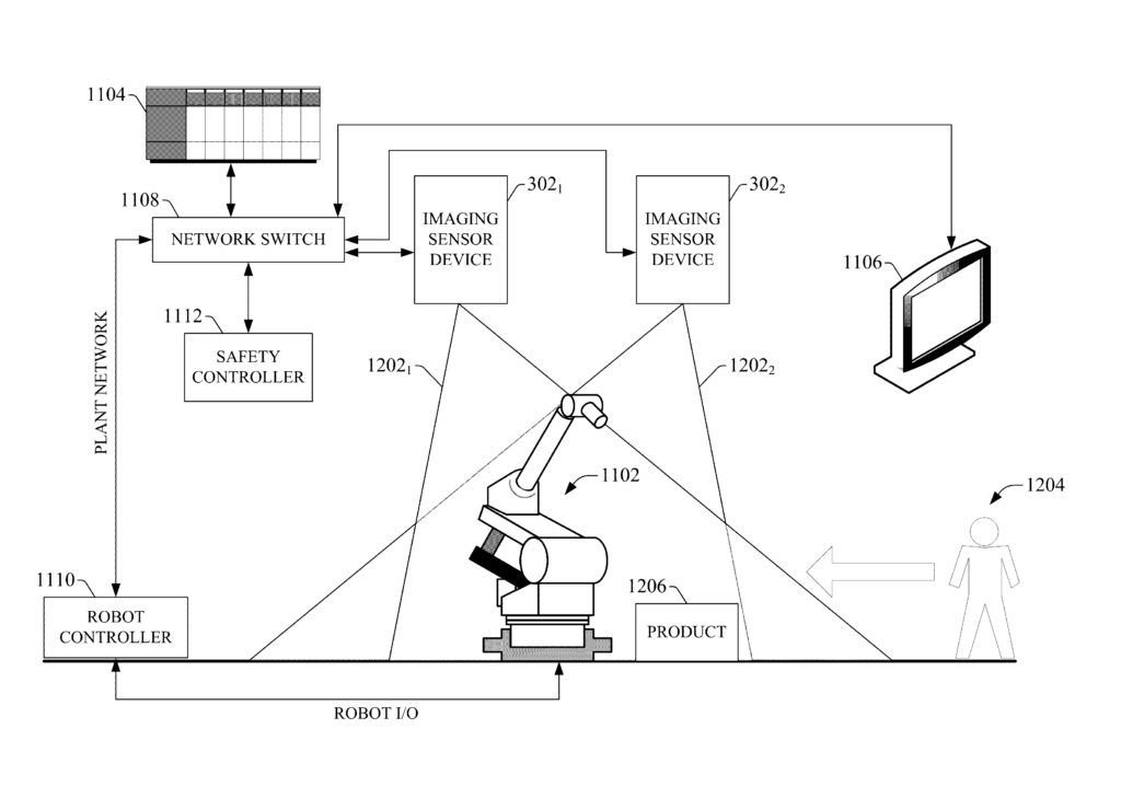
To address these and other concerns, one or more embodiments in the present disclosure provide a industrial safety monitoring system with an imaging sensor that is capable of performing 3D analysis on selected portions or subsets of the sensor’s pixels array. In some embodiments, an imaging sensor allows for a selection of pixels to be subjected to 3D analysis (time-of flight) in order to get distance information. The remaining pixel areas are processed with 2D image analysis. After the sensor has been trained on an area of interest, the user can select a horizontal line of pixels in the middle of the pixel grid (or along the upper or lower edge of the pixel grid) for 3D analysis. This will allow distance information and object identification to be managed for the area that corresponds to the chosen stripe. The sensor will perform 2D analysis, such as grayscale or RGB, on the non-selected portions of the pixel matrix to identify, classify and/or correlate the objects in the viewing area. 2D processing is faster than 3D, so by restricting 3D analysis only to those parts of the scene where distance information is needed, sensor response times are improved. The imaging sensor may also be configured to combine the results of 2D and 3-D analysis in order to obtain the speed, distance and trajectory of objects within the viewing area with high safety integrity. The imaging sensor can be configured to interface with a single or multiple pieces of industrial equipment, such as a robot. The imaging sensor can interface with industrial equipment (e.g. (based on the results of 2D and 3-D image processing), and can then send control instructions to industrial equipment via a hardwired or networked interface. The imaging sensor adds a layer to the control of industrial systems, allowing them to be controlled based on the objects, events, and movements within the monitored volume or area.
In some embodiments, an imaging sensor can be configured to dynamically modify or select the portion of the pixels array to which 3D analyses are to be applied, for example, based upon the detection of a certain object in the viewing area. In normal operation, for example, the imaging sensors may be configured so that they perform continuous 2D analyses on the entire array of pixels until an object (e.g. a person or trolley) is detected. is detected. The sensor can define a portion around an object, for example, when someone enters the viewing range of the sensor, for 3D analysis. This allows the TOF (distance information) to be tracked. This defined pixel area may be dynamically changed by the imaging sensor to follow the object, so that speed and distance information can continue to be tracked for the object while it remains in the viewing area.
In one or more embodiments the imaging sensor can also be configured so that it can identify, for a particular image, non-contiguous pixels belonging to a specific object. The imaging sensor can identify a person in the viewing area, even if they are partially obscured by the image. The imaging sensor can be trained to recognize two visible objects that correspond to human legs and then correlate them within an image to indicate a partially obscured human within the viewing zone. The sensor can track the correlated objects, as needed (e.g. by performing 3D analyses on the pixels corresponding to both objects), so that an appropriate safety output can delivered to a controlled system based on location and speed.
FIG. The block diagram in Figure 3 shows an example of a sensor imaging device 302 that is used to illustrate one or more embodiments. While FIG. Although FIG. In some embodiments, FIG. 3 can reside on a different device than imaging sensor device 302. Aspects of systems, apparatuses or processes described in this disclosure may be machine-executable component(s) embodied inside machine(s), for example, in one or multiple computer-readable media (or mediums) associated with one machine or more machines. These components can be executed by one or several machines (e.g. computers, computing devices, automation devices, virtual machines, etc.) and cause them to perform the described operations.
![]()
The “Imaging Sensor Device 302” can consist of an illumination component, a component for pixel array, a component for distance determination, an image component, an analysis component, a component to perform hazard and decision analysis, a component that analyzes images, an interface component, a processor, memory, and an interface component. In different embodiments, the illumination component 306, pixel array component 30, distance determination component 312, image analysis component 312, the hazard and decision component 314, the safety component 316, the interface component, processor 320 and memory 322 may be electrically or communicatively connected to each other to perform some or all of the functions of imaging sensor device 302. Some embodiments can include software instructions that are stored in memory 322 and then executed by processors 320. The imaging sensor device 302 can also interact with hardware or software components that are not shown in FIG. 2. The processor(s), for example, may interact with external interface devices such as a monitor, keyboard, mouse, touchscreen, display, or any other interface device. The imaging sensor device 302 can also have network communication components, as well as networking ports, for sending data from any of the components 304 306, 310 312, 314, 318, over a network.
Click here to view the patent on Google Patents.
Leave a Reply