Invented by David MORCZINEK, Maxim DOUBENSKI, Adam KERSNOWSKI, Mirela PETKOVA, Nikhil SHINDAY, Airworks Solutions Inc
Traditionally, creating CAD files required skilled designers and engineers to manually draft and design each component. This process was time-consuming, prone to human error, and limited to those with specialized training. However, with the advent of image analytics and machine learning, the creation of CAD files has become more automated and efficient.
Image analytics refers to the use of algorithms and computer vision techniques to analyze and interpret images. By applying these techniques to images of physical objects or prototypes, software can automatically extract relevant information and convert it into CAD files. This eliminates the need for manual measurements and drafting, saving time and reducing errors.
Machine learning, on the other hand, involves training algorithms to recognize patterns and make predictions based on large datasets. In the context of CAD file creation, machine learning algorithms can be trained on a vast amount of existing CAD files to learn the rules and patterns that govern their design. This allows the algorithms to generate new CAD files based on user input or specific design requirements.
The market for these methods is driven by several factors. Firstly, the demand for CAD files is increasing across various industries, including architecture, manufacturing, automotive, and aerospace. As companies strive for more efficient and cost-effective design processes, the need for automated CAD file creation becomes paramount.
Secondly, the advancements in image analytics and machine learning technologies have made them more accessible and easier to implement. This has opened up opportunities for smaller companies and individuals who may not have the resources to hire skilled designers or engineers. With automated CAD file creation, they can now generate professional-quality designs without extensive training or expertise.
Furthermore, the accuracy and precision offered by these methods are unparalleled. By eliminating human error and subjectivity, the resulting CAD files are more reliable and consistent. This is particularly crucial in industries where precision is critical, such as aerospace or medical device manufacturing.
The market for methods for automatically creating CAD files using image analytics and/or machine learning is expected to grow exponentially in the coming years. As the technology continues to evolve, we can expect to see further improvements in accuracy, speed, and usability. This will not only benefit established industries but also pave the way for new applications and innovations.
However, challenges remain. The algorithms used in image analytics and machine learning heavily rely on the quality and quantity of training data. Ensuring that the algorithms are trained on diverse and representative datasets is crucial to avoid biases and inaccuracies. Additionally, the integration of these methods into existing design workflows and software platforms may require further development and standardization.
In conclusion, the market for methods for automatically creating CAD files using image analytics and/or machine learning is poised for significant growth. This technology has the potential to revolutionize the design process, making it faster, more accurate, and more accessible to a wider range of industries. As advancements continue, we can expect to see increased adoption and innovation in this field, leading to further improvements in design efficiency and productivity.

The Airworks Solutions Inc invention works as follows
A nontransitory processor readable medium includes code that causes a processor receive aerial data with a plurality points arranged in an arrangement. A machine learning model uses an indication for each point as input in order to classify the point into one of a number of categories. A set of adjacent points and points with a shared category are identified for each point to define a particular shape out of a variety of shapes. By analyzing, with reference to a criteria, the position of each border point of a shape in relation to at least one point, a polyline boundary is defined for each shape. Each category includes a layer that contains each shape. A computer-aided design (CAD) file is created using the polyline boundaries of each shape, the layer and each category.
Background for Methods for automatically creating computer-aided design (CAD) files by using image analytics and/or machine learning
The embodiments and methods described in this document relate to the creation and/or definition of computer-aided designs files. More specifically, they describe how to create computer-aided designs files automatically using machine learning, image analysis, and/or computers vision.
The modern increase in capabilities of electronic devices has resulted in machines performing many tasks that were traditionally performed by humans. Computer-aided design software (CAD) can be used by a computer to create, analyze, or draw a design, drawing, or model. CAD software is used to create a model in two dimensions (2D) or 3D that includes and/or presents any information suitable, such as views of the model or units of measurement and/or scale. Tolerances, material properties and/or conventions. Computer-aided design (CAD), in many cases, has replaced the manual drafting of architectural plans, engineering drawings and blueprints.
In some cases, CAD is used to model a property or a plot of ground, and/or an area of interest. The model may include information about geological features, topography and/or manmade structures such as buildings, roads and/or other land features. In certain cases, detailed measurements of a part of the property can be taken and inputted into a computer program in order to create a 3D or 2D model of that portion (e.g. a site map, a survey of the site, etc.). Likewise, architects, engineers, builders, contractors, etc. Similar 2D or 3D CAD drawings and/or models can be created for structures already built on land, as well as future structures that have not yet been built. Although creating and/or defining such models or designs is more efficient than drafting and/or designing by humans, using pen and paper for example, certain known processes to create and/or define these models and/or sketches are still labor-intensive, time-consuming, and/or costly. Some of these processes require a large amount of computing power to create the 2D or 3D CAD model, as well as a large amount of computing power to view the 2D or 3D models and/or use them in CAD programs.
Accordingly, there is a need for automatically defining computer aided design files by using machine learning and image analytics.
Herein are described methods and apparatuses for automatically creating computer-aided designs files by using machine learning and image analytics. In certain embodiments, code is included on a nontransitory processor-readable media to enable a processor receive aerial data with multiple data points arranged into a pattern. As an input, the processor sends an indication for each point to a machine-learning model that classifies each point in a category out of multiple categories. The processor identifies a group of adjacent points in the pattern that share a category with that point. This allows it to determine a shape out of multiple shapes. The processor determines a polyline border for each shape by analyzing, with reference to a criteria, the position of each of the points associated with a boundary of that form relative to another point. The processor creates a layer that includes all shapes associated with each category. The processor creates a computer-aided file using each polyline boundary and each layer.
The embodiments or methods described herein are generally related to the creation or generation of computer-aided designs (CAD) files which provide or can provide one or more models or drawings of a site or property of interest. The CAD files can be generated automatically using image data taken or captured of the site. The models or drawings in the CAD file can be accurate digital representations of site plans, architectural drawings, or models of buildings. The models and/or drawing in the CAD file can therefore provide information related to the topography and/or geology of the land, as well as information about the buildings, roads and sidewalks on the site, or any other structures that are located there.
The reasons for this are numerous. For example, the CAD models may contain a greater quantity and/or quality of data than the images. Some of these reasons include, but are not limited to, a larger quantity or better quality of data for the objects in the CAD model compared to the corresponding data in the images, a more convenient way to access the data in the CAD model compared to the corresponding data in the images, the ability to modify, move, alter, update and/or revise the object in the CAD model, which is difficult to do in images, etc. The images of a site of concern can also be large files, which require a large amount of computing power when displayed on a computer display. In some cases, CAD images generated by the systems and/or method described herein may have a higher quantity or quality of data than the images, while the size of the files (e.g. compressed) can be smaller and/or the amount of computing resources can be lower (e.g. the computing device that executes the CAD programs can perform more efficiently). The CAD files created by the systems and/or method described herein are more accurate, and less likely to be subject to human error, than the known methods for converting images into 2D or 3D models.
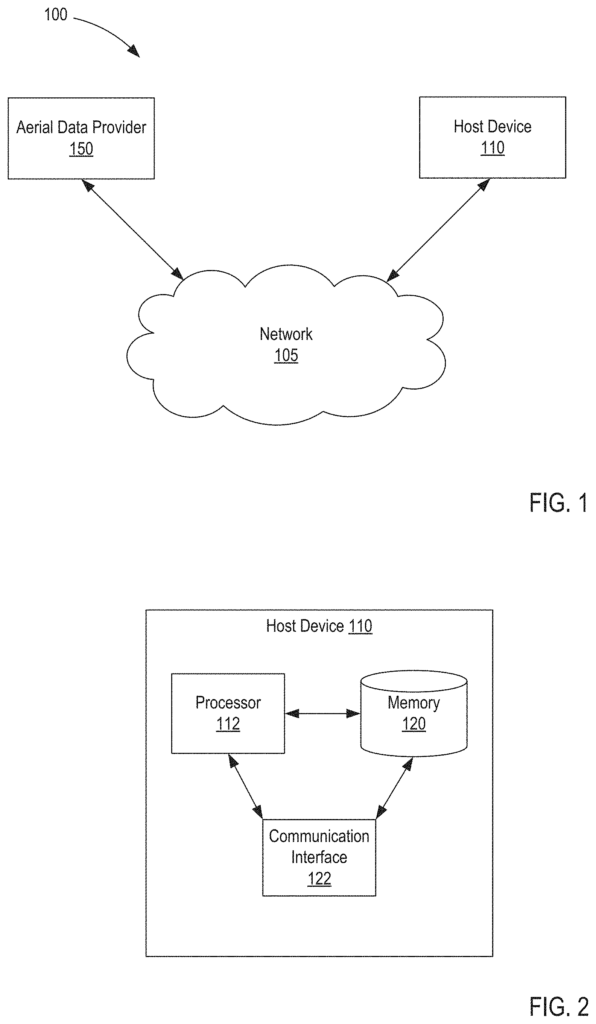
In some cases, a host can be configured to define and/or create one or more CAD (computer-aided design) files that are based in part at least on aerial data. Received from an aerial data supplier. The aerial data provider could be any device that is capable of capturing data, or any device, database, or repository that can store aerial data. The host device can then analyze the aerial information, identify and categorize the shapes that are represented in at least some of the data and generate a CAD model, drawing, or depicting the shapes. In certain instances, the categorization and/or identification of the one-or-more shapes can be done by one or several machine learning models. The aerial data, or the results of analyzing aerial data, can also be used as inputs to the machine-learning model to train it, for example to improve the accuracy and/or efficiency in the identification and/or classification of the one of more shapes. The embodiments described herein may be used to automatically create CAD files by using image analytics, computer vision and/or machine learning.
As described herein in more detail, the host device may be configured to process aerial data according one or several predetermined rules and/or methods. In certain instances, the host can be configured with a set processes, rules and/or instructions associated with segmenting images (e.g. photogrammetry or photograph data) in order to identify one or more shapes contained within that image (e.g. via machine learning). The host device may then execute a series of rules, processes and/or instructions that classify the shapes identified into a category corresponding to one or multiple layers in a CAD. The host device may then execute a series of rules, processes and/or instructions that are associated with converting each border of a shape from the image into a polyline bound of the shape (e.g. in a second form). In certain instances, the host can be configured so that it analyzes the polyline borders to create a smoothed-out, simplified and/or filtered boundary based on one or more thresholds. The host device will then create a CAD that contains shapes with smoothed or simplified polyline borders (e.g. shapes in second format), which correspond to the original shapes (e.g. shapes in first format).
In some embodiments, non-transitory computer-readable media include code that causes a processor receive aerial data with multiple points arranged into a pattern. The processor inputs an indication for each point to a machine-learning model that classifies each point in a category out of multiple categories. The processor identifies a group of adjacent points in the pattern that share a category with that point. This allows it to determine a shape out of multiple shapes. The processor determines a polyline border for each shape based on a set of criteria that analyzes the position of every point that is associated with a shape’s border relative to another point that is associated with that shape. The processor creates a layer that includes all shapes associated with each category. The processor creates a computer-aided file based on the polyline boundaries of each shape, and the layers for each category.
In some embodiments an apparatus consists of a memory, and a processor that is operatively connected to the memory. The processor can receive aerial data that includes multiple points arranged into a pattern. The processor is configured for an indication to be associated with each of the points as input to a machine-learning model that will classify each point in a set categories. The processor is configured for selecting a category based on predefined categories hierarchy. The processor is configured to identify for each point a group of points that are (1) adjacent to the point in the pattern, and (2) share a category to define a form from a multiple shapes. The processor is configured for generating a computer-aided file using each shape of the multiple shapes.
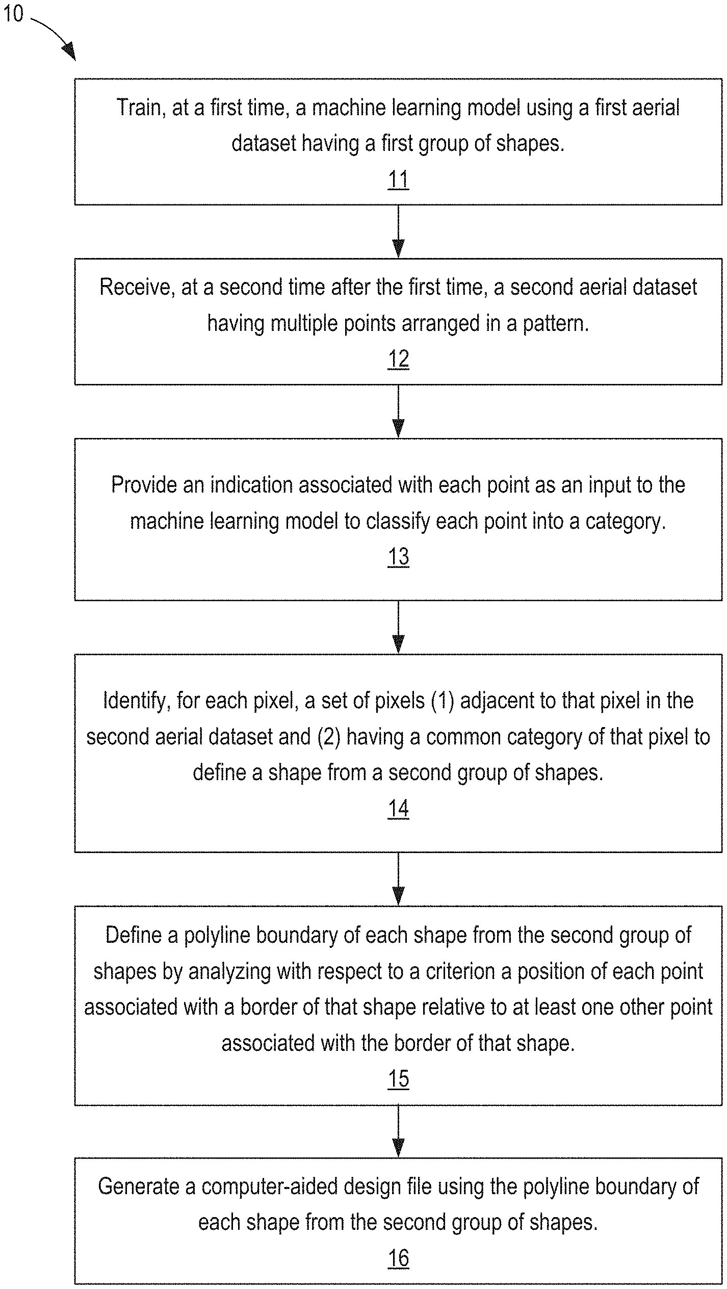
In certain embodiments, the method involves training a machine-learning model for the first time using a dataset of aerial shapes. Each shape is (1) labeled by a specific category out of a large number and (2) has a polyline border that encompasses the shape completely and is distinct from the polyline boundaries for the other shapes. A second aerial dataset with multiple points arranged into a pattern will be received a second after the first. A category is assigned to each point using the input from the machine learning model. A set of adjacent points in the pattern (2) that share a category with each other is identified for each point to define a form from a second group of shapes. The polyline boundary for each shape in the second set is defined by analyzing the position of every point that corresponds to the border of the shape with respect to the other points that are associated with that border. The polyline boundary is used to define a computer-aided file for each shape in the second set.
In some embodiments, the non-transitory medium-readable by a processor includes code that causes a processor receive aerial data with multiple points arranged into a pattern. The aerial data is filtered by the processor to create a group of points. The processor selects adjacent points in the pattern for each point of the set of multiple points to create a cluster. The processor creates a group of clusters by identifying at least one point from a plurality of points within each cluster, or if each point in a cluster meets an elevation criteria. The processor determines a shape based on a set formed by at most one cluster of the set of clusters, based in part at least on the regularity criteria of the at least one group. The processor creates polyline boundaries for each shape by analyzing, with respect to a criteria, the position of each of the points associated with a shape’s border relative to the other points associated with that shape. It then generates an CAD file using each polyline boundary.
The singular forms used in the specification are?a? ?an,? The words?an?,? Include plural referents, unless the context makes it clear that they are not. The term “an image” is a good example. The term ‘an image’ is meant to refer to a single or combination of images. Similarly, the term ‘a model? “is intended to mean a single image or a series of images,?a model?
The phrase “site of interest” is used in this document. “Site of interest” is a general term that refers to any property, unimproved or improved plot of land, planned or actual construction site, or any other portion of Earth’s surface of interest to an investor.
As used in this document, the term “aerial data” is defined as: In general, aerial data refers to all suitable data that is associated with a particular site and has been captured, scanned or recorded. It can also be taken from an aerial perspective. Aerial data may include any number of images (e.g. photographs) taken from the air of the site (or part thereof). When multiple aerial images are used, they can be taken at a similar altitude and can include overlapping or overlaying.
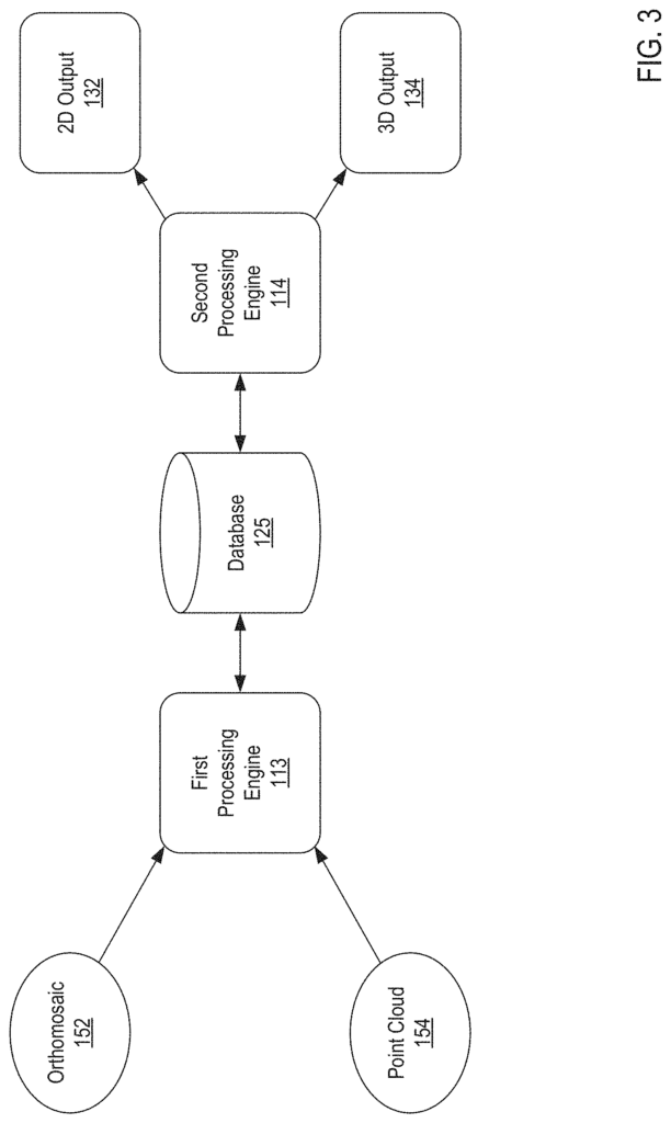
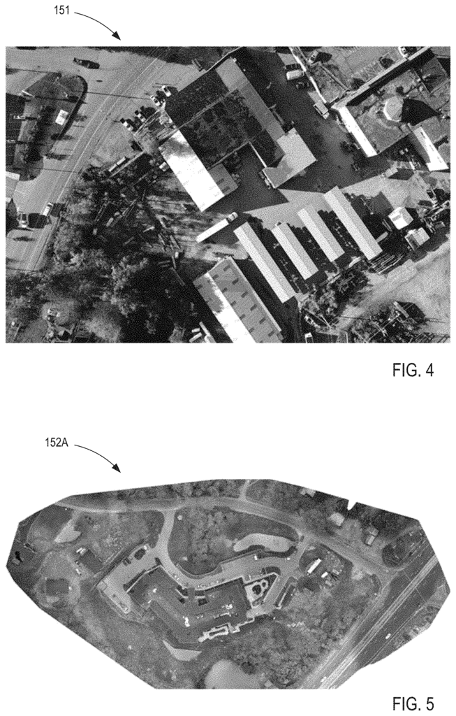
In some cases, “aerial data” can be data from or included in one or more orthomosaic images. Data from or data included in orthomosaics can be used. A orthomosaic can be one or more aerial photographs (e.g. photos of a site of interest), which have been geometrically rectified (also known as “orthorectified”). The aerial image should be a true representation of the Earth surface. The orthomosaic image can also be georeferenced so that it contains coordinates or a coordinate system, allowing it to accurately represent the location of the aerial image on Earth’s surface. Georeferenced orthomosaics can sometimes be saved or converted to a “geotiff”. The georeferenced orthomosaic images can be converted into and/or saved as a?geotiff? The above example is a specific method or process for producing an orthomosaic image and/or georeferenced images. However, the example is only meant to be an example and not a limitation. It should be understood, therefore, that other formats, methods and/or standards for georeferencing images are also possible.
In some cases, “aerial data” can be data from or included in a point cloud (e.g., a set of data points in space). Data from a point-cloud (e.g. a collection of data points in the space) can be included. In some cases, photogrammetry techniques and/or processes can be used to obtain and/or capture images of a particular site (e.g. taken from an airborne position), and then analyzed to produce a set (e.g. a pointcloud) of data points that can, for example model the topography at the site. Each point of the cloud (e.g. the data points generated by photogrammetry), as described above in relation to orthomosaics, can be georeferenced, allowing it to accurately represent its location on Earth (within an established tolerance). Each point can be georeferenced and also have data indicating the elevation of each point. The elevation data may indicate whether a data point is at ground level or not. The data points can be used to create a 3D overlay of Earth’s surface including data points that represent ground surfaces, trees, water bodies, sidewalks and roads.
In some cases, a “point cloud” can be created by combining data from photogrammetric methods with data generated using other methods, such as scans or analytic techniques. In some cases, photogrammetric data combined with range data, such as that generated by a LiDAR or any other suitable device, generally taken from an airborne position, can result in a set 3D data points. The use of multiple data sets (generated or captured via different modes) can be used to verify position data, and/or enhance position data. A point cloud can also be created using other methods or modes than photogrammetry. In some cases, a LiDAR scan can be used to generate a pointcloud without any additional photogrammetric information. The method or process described above is not intended to be a limitation, but rather a way to illustrate the possibilities. It is important to note that there are other formats, methods and/or standards for acquiring or using point cloud data.
In some cases, aerial data, or a part of it, can be taken directly from a scanner, camera, emitter, sensor etc. Other times, aerial data can be derived or calculated from one or multiple datasets. Although examples of aerial information are given above, it is important to note that aerial data may also include other data suitable for the site (e.g. any suitable aerial data, in additions to orthomosaics, point clouds, and/or non-aerial data).
Click here to view the patent on Google Patents.
Leave a Reply