Invented by James Cooper, Keeline Wilcox, Joseph Edward Clayton, Google LLC
Augmented reality (AR) and virtual reality (VR) have gained significant popularity in recent years, with a wide range of applications in various industries. As these technologies continue to evolve, one crucial aspect that manufacturers are focusing on is the comfort and usability of head-mounted display (HMD) devices. One of the key factors that contribute to a comfortable user experience is the airflow within the device.
Airflow plays a vital role in HMD devices as it helps regulate temperature, prevent fogging, and reduce discomfort caused by heat buildup. The market for airflow solutions in AR and VR HMD devices has witnessed substantial growth, with manufacturers continuously innovating to enhance user experience.
One of the primary challenges in designing airflow systems for HMD devices is maintaining a balance between comfort and functionality. The airflow should be sufficient to prevent overheating and fogging of the lenses, but not too strong to cause discomfort or distract the user. Achieving this balance requires careful engineering and design considerations.
Several approaches have been adopted by manufacturers to address the airflow requirements in HMD devices. One common solution is the use of small fans or blowers strategically placed within the device to circulate air. These fans are designed to be quiet and efficient, ensuring minimal noise and power consumption while providing adequate airflow.
Another approach is the integration of passive cooling techniques, such as heat sinks or thermal pads, to dissipate heat generated by the device’s components. These passive cooling methods work in conjunction with the airflow system to maintain optimal temperature levels and prevent discomfort.
Additionally, manufacturers are exploring innovative designs that incorporate adjustable vents or air channels to allow users to customize the airflow according to their preferences. This feature is particularly useful in scenarios where users engage in physically demanding activities, such as gaming or training simulations, as it helps regulate temperature and prevent excessive sweating.
The market for airflow solutions in AR and VR HMD devices is expected to witness significant growth in the coming years. As the demand for immersive experiences continues to rise, manufacturers will continue to invest in research and development to enhance the comfort and usability of their devices. This includes advancements in airflow systems, such as improved fan designs, noise reduction technologies, and more efficient cooling mechanisms.
Moreover, the market for airflow solutions in HMD devices is not limited to gaming or entertainment industries. Industries such as healthcare, education, and engineering are also adopting AR and VR technologies for various applications. These industries require HMD devices that provide long-lasting comfort and optimal airflow to ensure uninterrupted usage during critical tasks.
In conclusion, the market for airflow solutions in AR and VR HMD devices is growing rapidly, driven by the increasing demand for immersive experiences and the need for enhanced comfort. Manufacturers are investing in research and development to design innovative airflow systems that strike a balance between functionality and user comfort. As these technologies continue to evolve, we can expect further advancements in airflow solutions, contributing to an even more immersive and comfortable AR and VR experience.

The Google LLC invention works as follows
A head-mounted display device can include a housing with a cavity facing the user and an electronics compartment. In the electronics compartment, at least one fan can be installed. In a peripheral portion of a user-facing cavity’s wall, a plurality of intake port can be defined. At least one air outlet port can be defined on a wall of the electronics compartment. Between the electronics compartment and the user-facing chamber, a plurality of air channel may be present. The at least 1 fan can draw air from outside the housing into the electronics and user-facing cavities through the air intake ports, then discharge it through the air discharge port to cool the electronics and user-facing compartment.
Background for Airflow in an augmented or virtual reality head-mounted display device
A head-mounted display (HMD), also known as a mobile device, is a device that can be worn on the head by users to immerse themselves in augmented reality or virtual reality. Some HMDs can be mounted or seated against the face of the user, around the eyes. This allows the physical environment to be blocked from view and enhances the immersive experience.
The head-mounted display device can include: a housing, an optical component assembled installed in it, a user facing cavity defined by the first peripheral portion and by the optical assembly; an electronics compartiment defined by the second peripheral portion and by the optical assembly installed inside the housing, and at least a fan installed within the electronics section; a number of air intake ports in the peripheral wall of the user-facing portion; a number of air channels connecting both the user-facing portion and the electronics portion; and at the position of the at least
The cooling system may include at least one fan installed in the second cavity, at least one heat sink installed in the second cavity, at a position corresponding to an exhaust side of at the least one fan, and at the very last, a heat pipe in thermal contact with at the very last, the at the most, the at the at the most, the at the at the at the at the at the at the at the at the at the at the at the at the at the at the at the smallest, the at the smallest The cooling system can include at the least, a fan installed in a second cavity. At least, if the fan is located on the exhaust side, he heat sink. And at the least, if the heat sink is installed in corresponding position to the exhaust side, the heat pipe.
The drawings and description below provide details on one or more of the implementations. The description, drawings and claims will reveal other features.
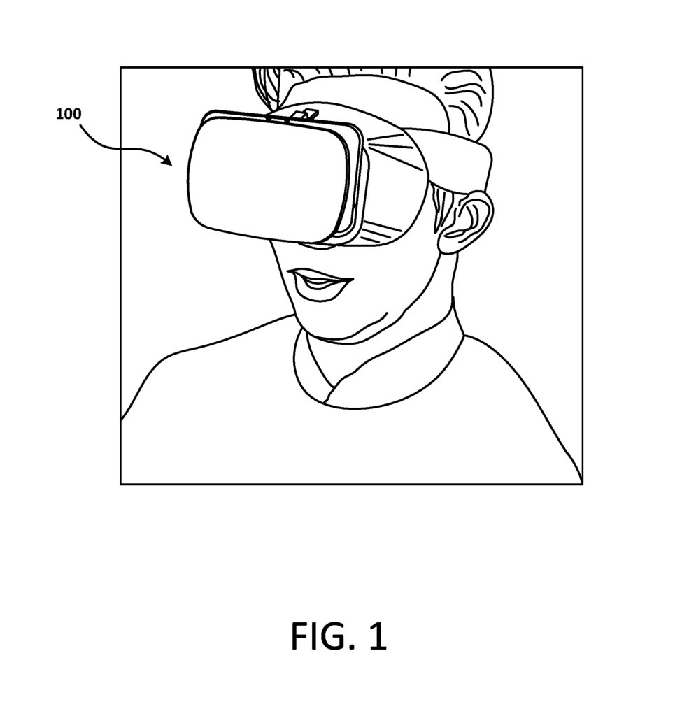
The HMD device can display audio content via an audio output unit included in or connected to the HMD, engaging the auditory senses of the user, providing the user an immersive virtual experience. The example HMD shown in FIG. The HMD 100, shown in FIG. 1, is seated or fitted against the user’s head, blocking their view of the physical environment outside the HMD 100. This arrangement may enhance the immersive virtual experience of the HMD 100 user by blocking out the ambient physical surroundings.
In some cases, the temperature or humidity of a space or cavity between the HMD 100, and the front of a user’s head, can increase as time passes, while the HMD 100 is still on the user’s head. The temperature or humidity level in this cavity facing the user may increase over time, which may be uncomfortable for the user and/or cause fogging of optical components in the HMD 100. This can interfere with the immersive experience of the HMD 100 and cause the user to feel discomfort. The HMD 100’s electronic components may be causing this problem. Overheating electronic components within an electronics compartment may also cause the HMD 100 malfunction.
According to the implementations described in this document, “In an HMD with a cooling system,” one or more fans can draw external ambient into the user facing cavity of the HMD in order to reduce, maintain, and/or reduce humidity in the cavity. The one or two fans can continue to operate to draw air into the electronic compartment from the user facing cavity to cool electronic components and/or cool one or several heat sinks as the air leaves the HMD.
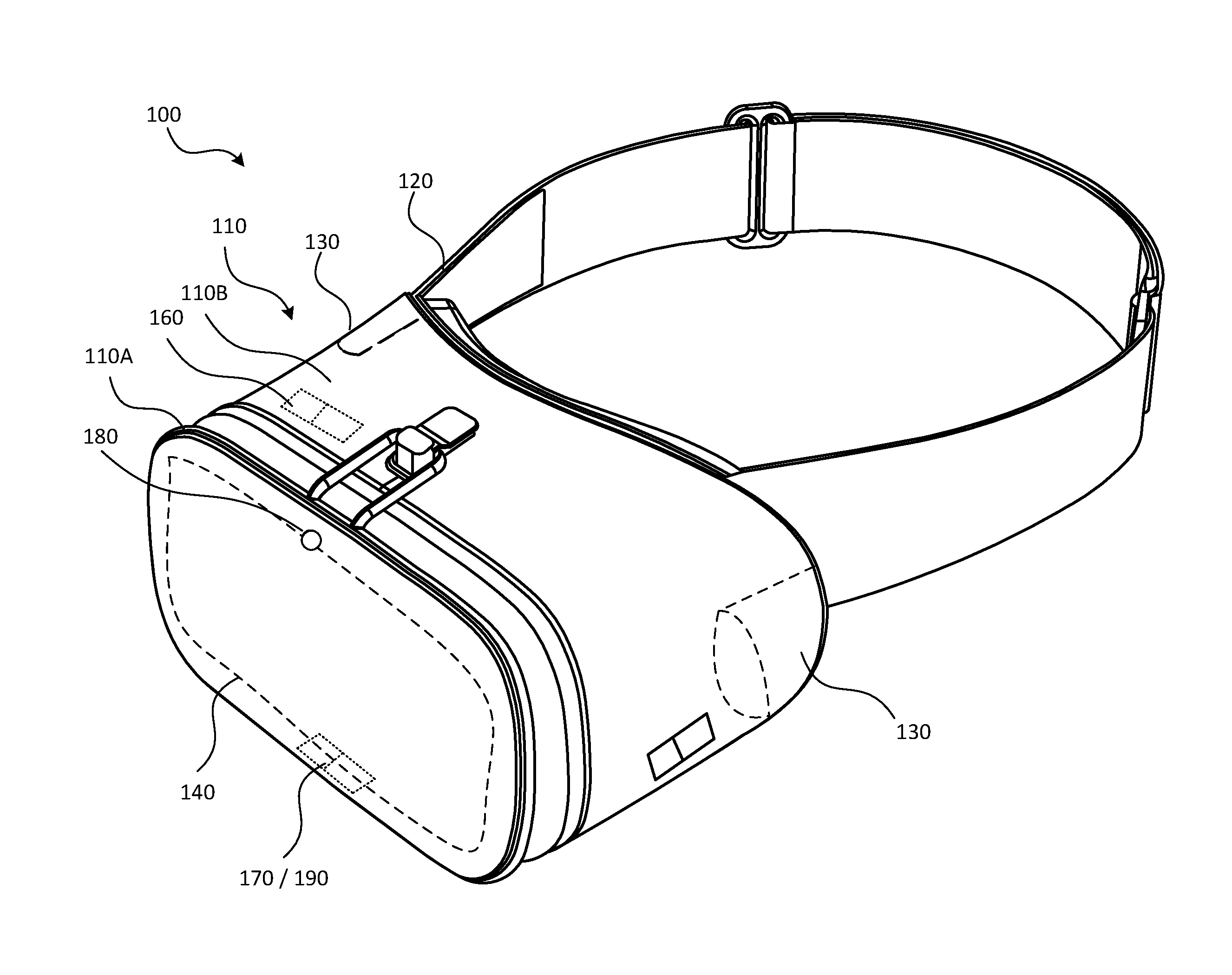
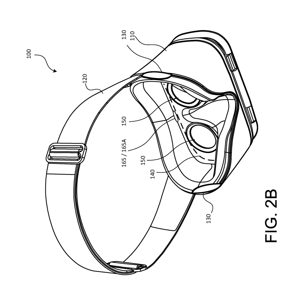
FIGS. “FIGS. 1. 2A is a front perspective view of the example HMD 100, and FIG. In particular, FIG. 2B shows a view from the rear of an HMD 100 housing 110, and its optical component assembly. FIG. “FIG.3 is a block-diagram of an electronic device example 300. This includes, for example, the HMD in FIGS. “2A and 2B.
As shown in FIGS. The example HMD 100 could include a frame 120 and a housing 110. Housing 110 may have a base portion and a front portion 110A. The display 140 can be mounted on the interior-facing side of the housing 110’s front portion 110A. In some cases, the HMD 100 may have a display that is installed into the housing 110. In some implementations the display 140 can be part of a separate electronic gadget, like a smartphone. This device may be removable and inserted or removed from the HMD 100 housing 110.
In some implementations, the HMD 100 may include a sensing system 160 including various sensors such as, for example audio sensor(s), image/light sensor(s), positional sensors (e.g., an inertial measurement unit including a gyroscope, an accelerometer, and/or a magnetometer), temperature sensor(s), moisture/humidity/moisture sensor(s), and the like. In some implementations the HMD 100 can include a sensor system 160 that includes various sensors, such as audio sensor(s), light/image sensor(s), positioning sensors (e.g. an inertial measuring unit including a gyroscope and/or an accelerometer), temperature sensors, moisture/humidity sensors, etc. HMD 100 can also include a controller 190 and a control system 175. These devices control various control systems to make the HMD 100 easier to operate. In some implementations the HMD 100 can include a camera to capture both still and moving pictures. The HMD 100 can include a gaze-tracking device 165, including one or multiple image sensors 165A, to detect and track the eye gaze of the wearer, which could be processed as an input.
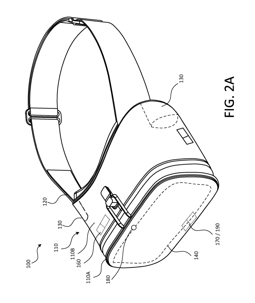
Audio components 130 can be attached to the HMD 100 or may be integrated into the HMD 100. In some implementations, audio output devices or speakers may be integrated into the HMD 100 housing 110 to direct audio output towards the ears of the wearer when the HMD 100 100 is worn. In some implementations auxiliary audio output device such as headphones, earbuds or over-the-ear headphones may be worn by the users to output audio content that is associated with the video content displayed on the HMD’s display 140.
In FIG. “A block diagram for an electronic device 300 such as the HMD 100, which is described above, can be seen. 3. The electronic device may include a sensor system 360 and a controller system 370. These may be similar to, respectively, the sensing and control systems 160 and 170 of the HMD 100 example shown in FIGS. 2A and 2B. The electronic device may include a thermal management system 365 to cool the device. The sensing system 370 may include, for instance, a light or audio sensor, image sensor, distance/proximity, positional sensor and/or temperature and/or humidimeter sensor. The control system may include, for instance, a power/pause device, audio/video control devices, optical control devices, transition control devices, cooling control devices, and/or any other devices or combinations of devices. The control system 370 and/or sensing system 360 may have more or fewer devices depending on the implementation and may be arranged differently. A processor 390 can be in communication with both the sensing system 360, and the control system. Memory 380 and a communications module 350 are also possible.
When the HMD 100 is positioned against the face or head of the user to display a virtual environment, the housing of the HMD 100 can be placed on top of it, as shown in Figure. 1. The HMD 100 being seated against the user’s face forms a barrier or seal that prevents light from entering into the HMD 100 housing 110. This arrangement can enhance and facilitate the user’s immersion into the virtual environment. However, it may also cause discomfort to the user. The temperature and/or humidity in the area between the user’s face and the lenses (hereafter referred as the “user-facing cavity”) may increase with time due to the body heat of the user or the operation of electronic components within the HMD 100. These elevated temperatures and/or humidities may, in some cases, cause fogging on the lenses 150 that are exposed to (e.g. disposed within) the user-facing cavities, blocking the view of the display. The discomfort or reduced visibility can reduce the user’s enjoyment of the immersive virtual world. The HMD 100’s electronic components may malfunction due to high temperatures.
In an HMD, according to the implementations described in this patent, a quiet and lightweight cooling system can be used to cool both the electronics compartment and the user’s cavity, with little or no impact on its external profile.
FIGS. The schematic views 4A-4E show an example HMD 100 with a cooling system in accordance to the implementations described herein. FIGS. The scale of the figures 4A-4E is not always accurate. Rather, some aspects of the HMD 100 example are illustrated in FIGS. “4A-4E can be exaggerated to make the illustration and discussion clearer.
FIG. “FIG. 4A. 4A. The example HMD 100 can include a cavity 420 or user-facing cavity, which is defined between the face or head of the user, and the optical component 150 of the HMD 100. The peripheral walls of base portion 110B may define an outer peripheral portion for the user-facing chamber 420. The HMD 100 can also include a second compartment 440 or cavity 440 in which the electrical components of HMD 100, such as the controller, processor, and so on, are housed. The optical component assembly 150 and the peripheral walls of front portion 110A may define the electronics compartment 440. The optical component assembly may essentially separate the electronics compartment from the user-facing chamber 420.
The HMD 100 can include a cooling device, such as at least one fan, 410, installed in the housing, for instance, in a section of the electronics compartment, 440, shown in FIG. 4B. As shown in FIG. 4B, the HMD 100 can also include a number of air intake areas formed on the peripheral portion of the housing 110 and a number of air channels that guide air into the HMD 100. 4B. In certain implementations, cooling systems may include heat pipes 470 or heat sinks 460. 5B to remove heat from electronic components within the electronics compartment. The cooling flow produced due to the suction generated by the atleast one fan 410 when the air is discharged out of the HMD 100 may also cool the atleast one heat sink. The at least heat pipe 470 can be in thermal communication with a portion of the housing. The thermal contact between at least one of the heat pipes 470 and housing 110 can allow the heat pipe to transfer thermal energy from electronic components within the electronics compartment to the outside of the housing.
In particular the operation of at least one fan may cause ambient air from the exterior to be drawn into a user-facing chamber 420 via the air intake areas formed in the peripheral wall portion surrounding the user facing cavity 420 of the housing 110, as shown by the arrows 430 in FIGS. The arrows A1 shown in FIGS. 4A and 4B illustrate the flow of ambient external air through the user-facing cavity 420. This flow of external ambient air through the user facing cavity 420 can cool the cavity and reduce the temperature and/or humidity in the cavity, reducing or eliminating fogging on the optical components that are exposed to the cavity. The air drawn from the user facing cavity 420 may be directed through the air channels towards the electronics compartment by the continued operation of at least one fan. In some implementations, for example, the continued operation of at least 1 fan 410 can cause air from the user-facing chamber 420 to be drawn through the air channels 450, toward the electronics compartment. 4B. This air, e.g. cooling air, drawn into the HMD’s electronics compartment can cool the electronic components in the electronics enclosure 440. The at least one fan may continue to operate, causing cooling air to flow over the electronic components within the electronics compartment for cooling and be discharged out of the HMD 100 in the direction indicated by the arrows A4 as shown in Figure. 4B.
In some implementations the plurality air intake areas or air intake ports may be defined on a bottom or top surface 111, and/or the right or left lateral surfaces 113 or 114, of the base portion of the housing 110. In some implementations the air intake ports 430 defined in the base portion 110B of the housing may be larger than those formed in the bottom or top surface 112. In some implementations all air intake areas 430 can be of a similar size. In some implementations, for example, all air intake areas 430 can have the same cross-sectional area. The air intake areas can be different sizes in some implementations. In some implementations the air intake area 430 can be covered with fabric, mesh, or foam, which allows air to pass, while maintaining a certain level of transparency to prevent ambient light from entering into the confines 110 of the HMD 100.
FIG. “FIG. 4C shows a perspective rear view of an example HMD 100 as shown in FIG. In 4A, a portion of base 110B of housing 110 is shown with dotted lines. FIG. The example HMD 100 in FIG.4D is shown from the rear perspective. The optical component assembly 150 has been removed from 4A to illustrate the position of the first and second air channels 450A and 450B. FIG. The example HMD 100 in FIG.4E is shown from the front perspective. In FIG. 4A, a portion of front portion 110A is shown in dotted line to illustrate the position of the first or second air channels 450A and 450B that lead into the electronics compartment. As shown in FIG. 4A, in some implementations two fans 410 can be installed within the electronics compartment. 4E. In some implementations more or fewer fans (such, for example the fan 410), can be included in the HMD 100, to generate the desired amount of suction and corresponding air flow through it as described herein.
In some implementations the terminal ends of air channels 450 can be positioned in order to direct air in the electronics compartments 440 according to the suction force created by the fan(s). The terminal end of each air channel 450 may be separated from the front surface 115 on the front portion 110A. This gap allows air to pass over electronic components such as the processor and/or controller, which are housed in electronics compartments, and be drawn into the HMD via the fan(s).

Click here to view the patent on Google Patents.
Leave a Reply