
Invented by Kaipo Chen, Individual
One of the key advantages of smart home-care lighting systems is their ability to create personalized lighting experiences. With the use of smart technology, these systems can be easily controlled and customized to suit individual preferences. Whether it’s adjusting the brightness, color temperature, or even creating dynamic lighting scenes, users have the flexibility to create the perfect ambiance for any occasion.
In terms of energy efficiency, smart home-care lighting systems are designed to be highly efficient, reducing energy consumption and lowering electricity bills. These systems often incorporate LED technology, which is known for its energy-saving properties. Additionally, the ability to schedule lighting patterns and automate lighting controls ensures that lights are only on when needed, further reducing energy waste.
Another significant advantage of smart home-care lighting systems is their impact on health and well-being. Research has shown that lighting can have a profound effect on our mood, productivity, and sleep patterns. Smart lighting systems can mimic natural light patterns, adjusting the intensity and color temperature throughout the day to promote a healthy circadian rhythm. This can help regulate sleep patterns and improve overall well-being.
Furthermore, smart home-care lighting systems can also be integrated with other smart devices and home automation systems, creating a seamless and interconnected home environment. For example, these systems can be synchronized with smart thermostats, security systems, and voice assistants, allowing users to control multiple aspects of their homes with a single command. This level of integration enhances convenience and simplifies daily routines.
The market for smart home-care lighting systems is expected to continue its growth trajectory in the coming years. As technology advances and becomes more accessible, more homeowners are likely to invest in these systems to enhance their living spaces. Additionally, the increasing focus on sustainability and energy efficiency is likely to drive the demand for smart lighting solutions.
In conclusion, the market for smart home-care lighting systems is expanding rapidly due to their numerous benefits. From personalized lighting experiences to energy efficiency and health benefits, these systems offer a range of advantages for homeowners. As technology continues to evolve, the market is expected to grow even further, providing homeowners with innovative and convenient lighting solutions for their homes.
The Individual invention works as follows
A smart home care lighting system” includes a lighting unit with a light-transmitting portion. The lighting device includes an illumination module to illuminate, a detector module that detects an external environment, an alarm and sound module that can be used in conjunction with the detection module to indicate and alarm, and an imaging module which captures and records images. A microprocessor, and a main controller module are also arranged in the lighting device for transmitting and saving personal habits and health data. The device can capture images in a 360-degree view range that doesn’t overlap. It can also be operated with the main control unit to determine what action is needed.
Background for Smart home-care lighting system
The present inventor has been working in the field of research and study and manufacture of LED (Light-Emitting Diode) for years and have previously proposed various surveillance/monitoring systems that are combined with lighting devices and have collected experiences of use and feed back from users of similar devices of this kind so as to full aware of the needs of the general consumers in this respect. The remote monitoring and surveillance devices for home care that were briefly discussed above, if built as a standalone device, would be perfect for the needs of home care, and provide a more intelligently controlled household surveillance environment.
For example, US Patent Publication No. 2008/0177646 A1 describes a remote monitoring system for a workplace, which includes employee time tracking. The data from biometric scans on site, along with images of surveillance are transmitted through a network, to the management end, in order to track the behavior and movement of employees. This system is not convenient to use because it requires an additional device. Japanese Patent Application No. The Japanese Patent Application No. The main disadvantage is that it is difficult to detect abnormalities in the human body with accuracy and efficiency. Also, the detection range is usually limited, which makes it hard to use this device for household applications or environments where interference is present.
The present invention is a lighting system that combines multiple techniques for detection, remote surveillance, and monitoring. It is designed to improve the detection capabilities of electrical appliances that are commonly used in the home environment, and determine the physical condition of a person by combining the system with corresponding devices.
The present invention is a smart lighting system for home care that includes a device with a cover, at least part of which can transmit light. The interior of the lighting device contains an illumination module to provide lighting, an imaging module that captures images at non-overlapping distances, a detection and alarm module which indicates and notifies detected environmental conditions, and an audio effect module. The modules are electrically coupled to a main controller module. The main control unit includes a chip that transmits information to establish connection, for example, with a tablet computer or smart phone, handheld device or wearable devices, and a system for in-vehicle (IVI) information. The main control module can also be used to compare data in order to activate/deactivate a function. The main control module can also store data about a particular user to create a personal health record.
The present invention makes use of an image pickup to increase the range of image capture to 360 degrees. It is also capable of integrating the information obtained through detection conducted by the other constituent modules and transmitting it to the main control module. Also, the present invention allows for the connection with household appliances to better integrate the home environment according to its setting values, to be more intelligent, to better suit personal habits and preferences and to provide better protection for the health of home members, as well as improving living quality and safety. The present invention is described in conjunction with drawings to help better understand the technical solution used in the invention and its advantages.
The summary and objectives presented above are only a short introduction to the invention. The following detailed description and claims of the invention should be read with the accompanying drawings to fully understand these and other objectives of the present invention, as well as the actual invention. In the drawings and specification, identical reference numbers refer to identical or comparable parts.
The detailed description of the invention and the accompanying drawings will reveal many other features and advantages to those skilled in the art. A preferred structural embodiment that incorporates the principles of the invention is illustrated as an example.
The following descriptions are only exemplary embodiments and do not intend to limit in any way the scope, applicability, or configuration of the present invention. The following description is intended to provide a practical illustration of how to implement exemplary embodiments. The function and arrangement can be changed in various embodiments without affecting the scope of invention, as stated in the claims.
The drawings and a detailed general description of the invention will help you better understand the invention. The present invention is a smart lighting system for the home.
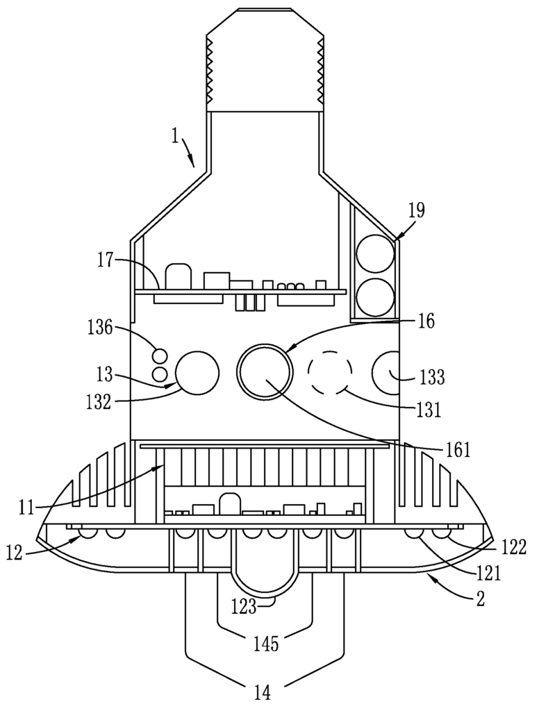
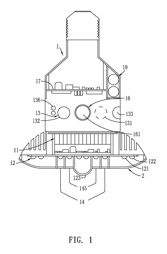
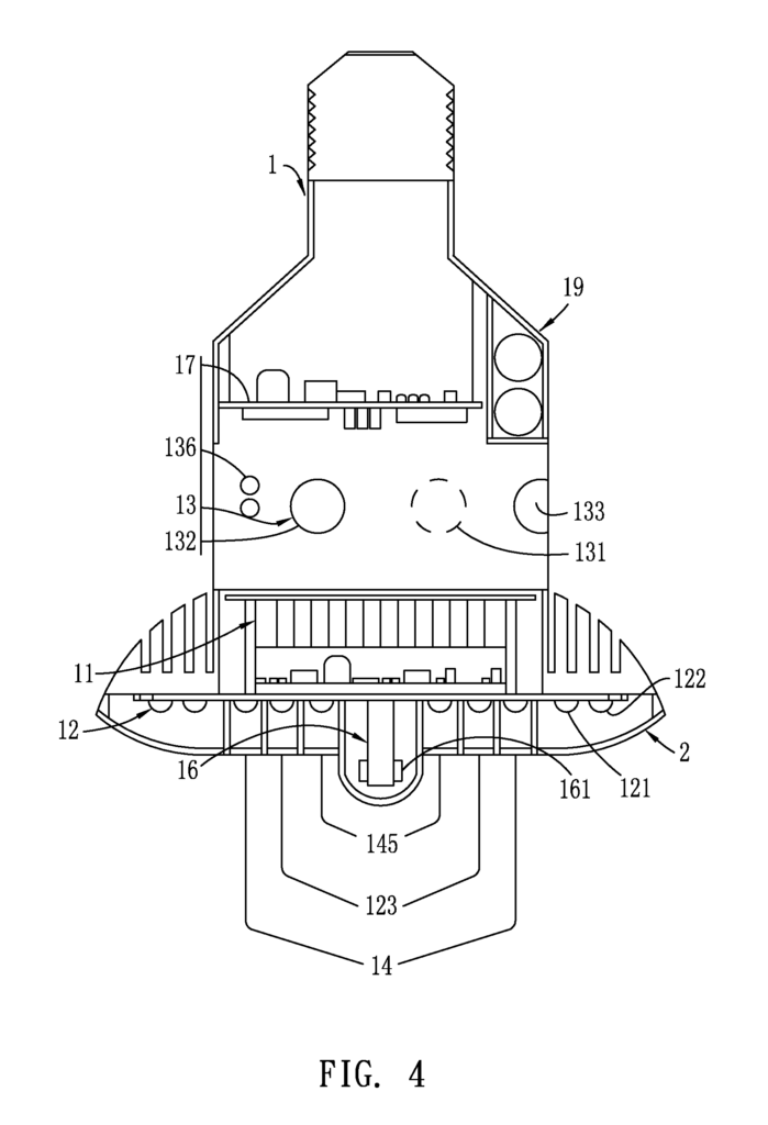
Shown in FIGS. The invention comprises: a lighting unit (1) that includes at least one light-transmitting cover (2), which is integrally formed or alternatively separate from the device, or The camera(s), (161) may also be a unitary assembly with two or more lenses in its interior to achieve the goal of being free from dead zones. However,
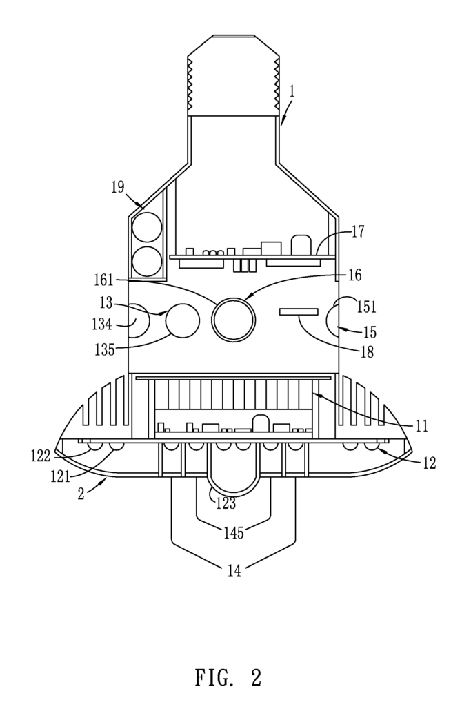
The main control module (11) is driven by a power board (17), which supplies power. The chip can be used to establish connection via WIFI, Bluetooth and wireless control, for example, with a tablet computer or smart phone, handheld or wearable devices, in-vehicle information systems (IVI), or a device that is capable of collecting and storing user data to create a personal health database (PHD). The main control unit (11) is located in the interior of lighting device (1). It is electrically connected with the modules/components mentioned so that it can perform an operation to compare the information provided thereto to preset thresholds stored in the microprocessor included in the main controller module (11). This information is then processed and identified to activate or deactivate a related function. The lighting device (1 is also provided with at lease one memory card (18) slot for the transfer and carrying of recorded images or to increase an additional time period available for recording images. Each of the modules above can be made as a single “board” Each of the above-discussed modules can be made in the form of a single?board? or multiple?boards. “But is not limited to so.
The detection module (13) consists of: a living object identification module (131), which detects the location and performance of an object (3); a humidity/temperature module (132), which detects the temperature/humidity outside the illumination device (1); a smoke detector module (133), that detects smokes outside the illumination device (1); a gassensor module (134), that detects harmful gasses outside the illumination device (1); an airsensor module (135), that detects suspended particles in the atmosphere outside the lumina
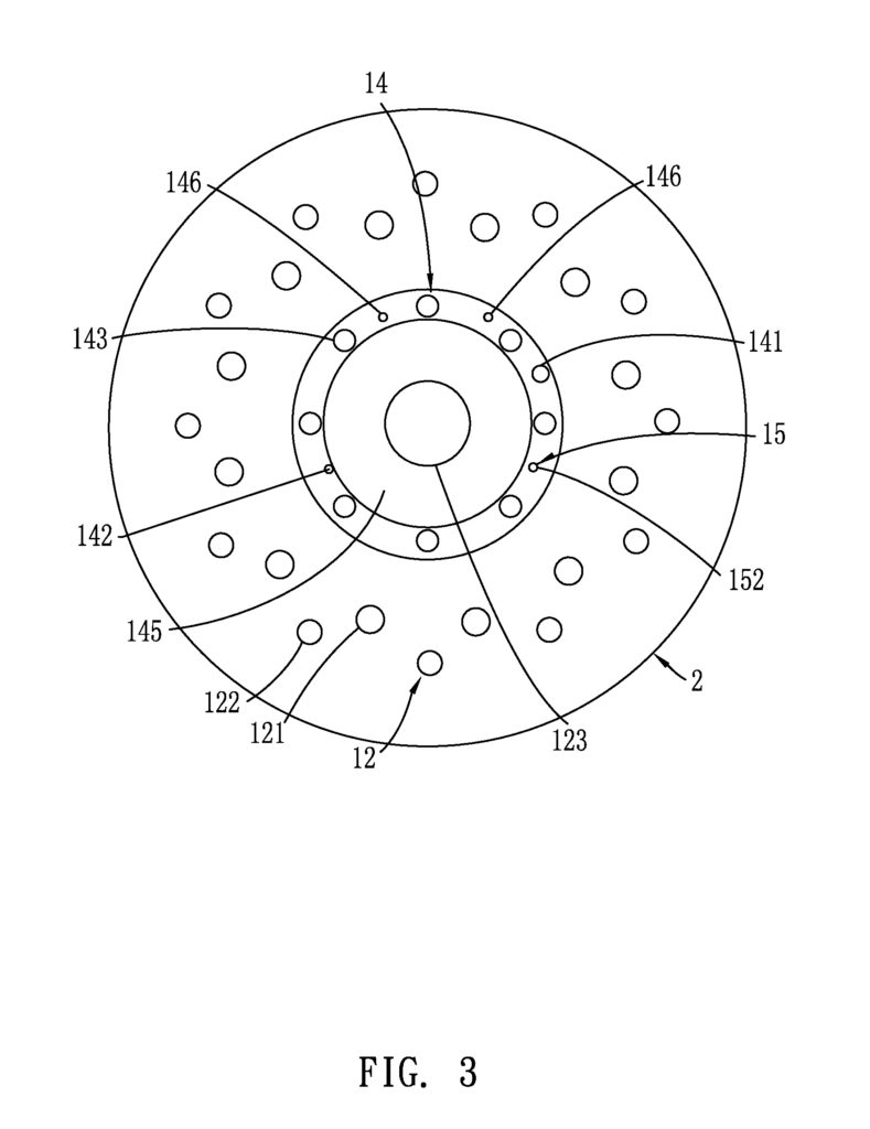
The illumination module (12), which is a combination of a warm-light LED (121), cold-light LED (122), as well as a secondary illumination (123), has an annular arrangement and is placed at the center of the lighting device (1). The secondary illumination (123) is in a circular form, and placed at the center of the illumination device (1). The warm light (121), cold light (122), and light board (122) are arranged around it in a dual-layer arrangement. Warm light LEDs are located in the inner circumferential circle or layer, and cold light LEDs are located in the outer circumferential circle or layer. The secondary illumination light (123) also includes a light-sensing element in its interior, so that the illumination module (12), by using the main control module (11) can automatically adjust the light to match the environment, or it can be controlled by an external input.
The indicator light assembly (14) consists of an IP setting light (141), temperature/humidity light (142), smoke/gas alarm (143), gas indicator (144), air quality indicator 145, and smoke indicator 146. All the indicators are driven to emit light as an indication or reminder on the basis of information obtained by each of its constituent modules in the detection module (13) that is fed back to the main controller module (11), with the number of indicators or light being increased or decreased based on an actual need.
Further, a backup power chamber (19) is included in the interior of lighting device (1) to receive installation of a commercially available power supply device. The backup power compartment (19) is electrically connected to the previously discussed power supply board (17) for supplying additional electrical power to drive the entire household surveillance/monitoring system in case of insufficiency or shortage of power supply. The sound effects module (15) consists of a microphone (152) as well as a speaker (151) for the purposes of voice control and broadcasting, receiving and recognition.
Further with the functions provided above, the gas sensor (134) detects harmful fumes in the atmosphere and the smoke detector (133) detects the smokes in that environment, such that the smoke/gas alert light (143), corresponding to them, transmits a message to a mobile device and begins to flash and broadcast for alarming, when a result of detection exceeds a certain threshold. When the most dangerous level is reached, the data and images are sent to the fire department. In normal operation, the smoke indicator (146), and gas indicator (144), are lit to recognize normal operation. In order to prevent common disasters and hazards such as gas explosion and fire, the two sensor modules must be kept in an active condition. The air sensor module (135) is primarily used to identify or track air or atmospheric quality. It generally detects suspended particles in the air or atmosphere, transmits messages related to that, and provides an air quality indicator (145) to correspond to it. This air quality display emits different colors for extended periods to indicate current air quality. Blue light indicates normal, yellow for acceptable, and red for low quality. However, colors can be varied during manufacturing, not just the ones mentioned above. The humidity/temperature module (132), when used, detects the temperature and humidity in air or atmosphere. This data is fed back to main control module (11) which then transmits messages to wireless devices.
The chip in the main control unit (11) processes the information acquired or captured by the image pick-up module (16), in order to determine the temperature and movement of the object (3), as well as determining if it is a person or pet. The living organism identification module (11) detects location and body performance and is usually embodied in a Doppler-radar, which can acquire data through frequency and amplitude. The material used to create the lighting device (1 ) does not affect the living organism identification module (131). It can therefore be hidden in the interior of the device for aesthetic purposes. The operation is based more specifically on a signal moving in a high-frequency band of the breath signal. This means that when a breath is detected and based upon a signal moving, it can be determined that a resident is moving abnormally within a predetermined period of time. Standing wave analysis can expand the detection range and improve accuracy in detecting abnormality. The information obtained from such detections can be sent back to the main module (11) and recorded in the PHD. In the event of an abnormality, the images and data so detected can also be transmitted to the hospital for remote medical treatment instructions. In general, the IP setting indicator (141) is provided to allow instructions to be set for the image pick-up module (16). The main control module chip (11) can use voice, wireless, or infrared control to connect to the detection module (13). This allows automatic control of household appliances such as air cooling/heating, air purifying, televisions and lights. The main control module (11) may be equipped with WIFI, Bluetooth or other communication technologies and can conduct detection by connecting to the door/window sensor corresponding to it. Sensors mounted on doors and window can be connected to main control module (11) to identify intrusion through doors and windows. The main control module (11) will activate the image pickup module (16), and give an instruction for the operation to be carried out, such as making the illumination (12) or alarm module (14) flashing, lighting or announcing, and driving the sound effects module (15) to begin broadcasting, notifying the user, or reporting to the police stations, to greatly improve the home security.
The camera (161) that covers a 360-degree range can also be used to achieve a better and wider range of surveillance or monitoring. This allows for preventing an event by entering a user name list in advance. The camera (161) can also provide a wider and better range of monitoring or surveillance, as it covers 360 degrees. This allows for a list of users to be created in advance, before an event happens, to prevent the event. In addition, if the user does not respond to the reminders, and the data continues to increase to an extremely dangerous level and there is no response, the data may be sent to the fire department via a network.
In a second embodiment, shown in FIGS. The image pickup module (16), which is shown in FIGS. The secondary illumination light (123) can also be adjusted to the position at which it is placed. The first and second embodiments both provide a spherical-bulb design. Although only minor modifications have been made to the structure, the applications of the invention can be extended to different lighting fixtures with different spaces.
As shown in FIGS. The lighting fixtures shown in the drawings include, in order, a ceiling lamp, an embedded light and a baylight, as well as two other types of embedded lights. The ceiling light shown in FIG. The lighting device (1) is shown in FIG. 7 with a small interior. At least one part of the light-transmittable covers (2) can be seen. In the interior of the lighting device (1), there are the illumination module (12), detection module (13), alarm module (14) and sound effect module (15). The image pickup (15) is a camera (161) that is arranged inside the lighting device (1) in a way to prevent the capture of images repeatedly. In the interior of the lighting device (1), a main controller module (11) is also provided. The main control module (11) electrically connects to the modules above for connection and determination with household appliances. This allows images captured by image pickup module (16), and detected information from all modules to be further analysed to provide a corresponding instructions. The bottom view shows that the image pick-up module (15) is at the center, and that the air quality indicator (145), secondary illumination light (123) and detection module (13) are sequentially arranged toward the outside. In the outermost circle there is a warm light LED (121) and a cold light LED (122). This arrangement can be used to reduce the amount of space required and is suitable for lighting fixtures with small interiors. Referring to FIGS. “Figures 12 and 13 show two different embedded light structures, with the same interior structure as the previous embodiments. However, the replacement of these lights is made easy by pressing and pushing, which makes inspection and maintenance easier.
The present invention is a smart home-care system that comprises a main controller (11) which includes a chip for connecting to household electrical appliances and a chip for storing PHD. It also includes an illumination module (12), alarm module (14), and sound effect module (15), all of which can be combined to achieve home care for health and security of members of the home in a dead-zone free and extended coverage range manner. The present invention has a lower cost than similar home-care devices and does not require additional sensor devices. It also allows for the storage of user data and is more flexible in its application.
Click here to view the patent on Google Patents.
Leave a Reply